 Sagar 001
In the previous GNSS interfacing tutorial we have seen the location readings in GPRMC and GPGGA format on the serial monitor in Arduino IDE. We are using the same RYS8830 GNSS sensor which has a very small form factor and high gain small antenna on top.
This RYS8830 is developed by Reyax technologies, here we are using the evolution board that comes with cp2102x USB to serial chip. The communication is to be setup between the microcontroller and UART(RX-TX) bus of the GNSS. As a microcontroller we are using ESP8266 NodeMCU.
Problems in interfacing:
As you know RYS8830 is a low power GNSS module and works on a voltage logic of 1.8v (max). here the problem is in voltage logic matching, because we can communicate on the high logic data line this will damage the module. Our ESP8266 NodeMCU works on 3.3volts, to solve this problem we have to design a logic level convertor. And using the linear regulator we can power up the both sides of logic level convertor with different voltages.
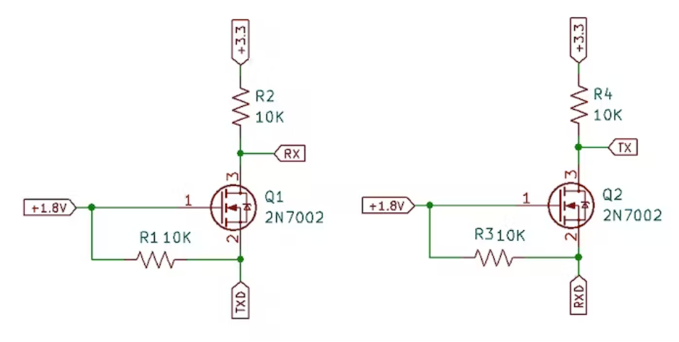
A logic level convertor is a device which is used to match the logic data convey on data power lines. Here I have shown the basic principle with the help of diagram.
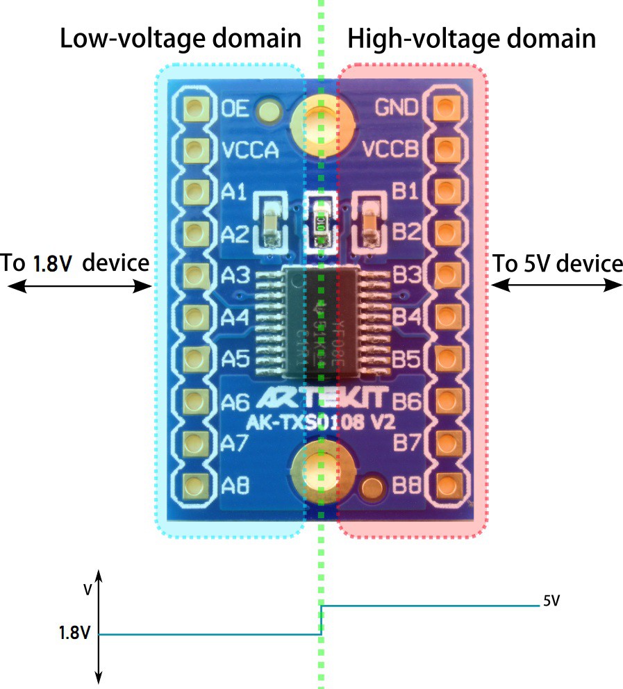
Either we can design the logic level convertor using 2 similar field effect transistor or there are CMOS IC available in market which will do the same. I have one lane around me here which supports up to 8 channel and the basic operational diagram is given below. you can see the datasheet of my logic level convertor (TXS0108E) from here.
Components required:
- ESP8266
- TXS0108E Logic Level Converter
- RYS8830 EVB
- SSD1306 1.96" OLED Display
- Custom PCB
- 5V battery power supply
- Jumpers and wires
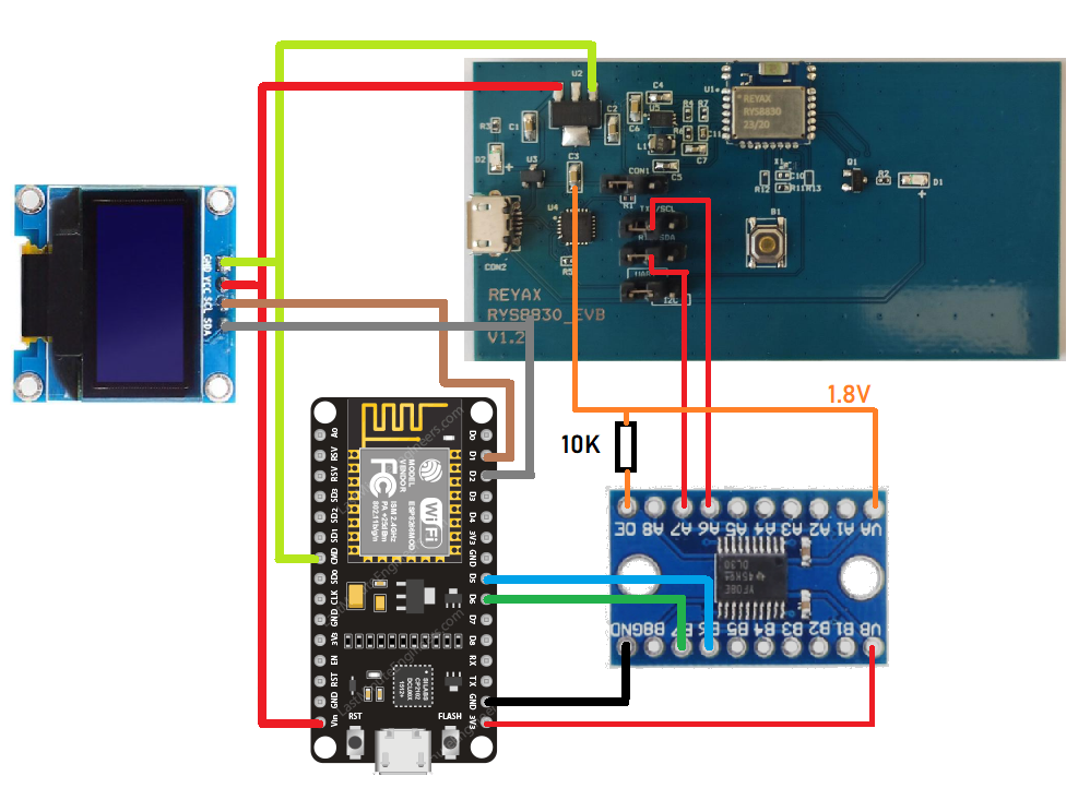
Circuit description and interfacing:
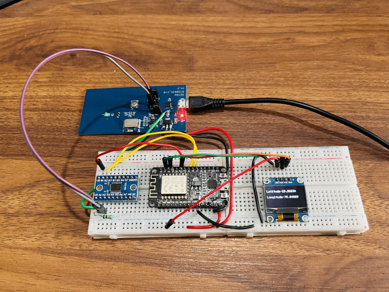
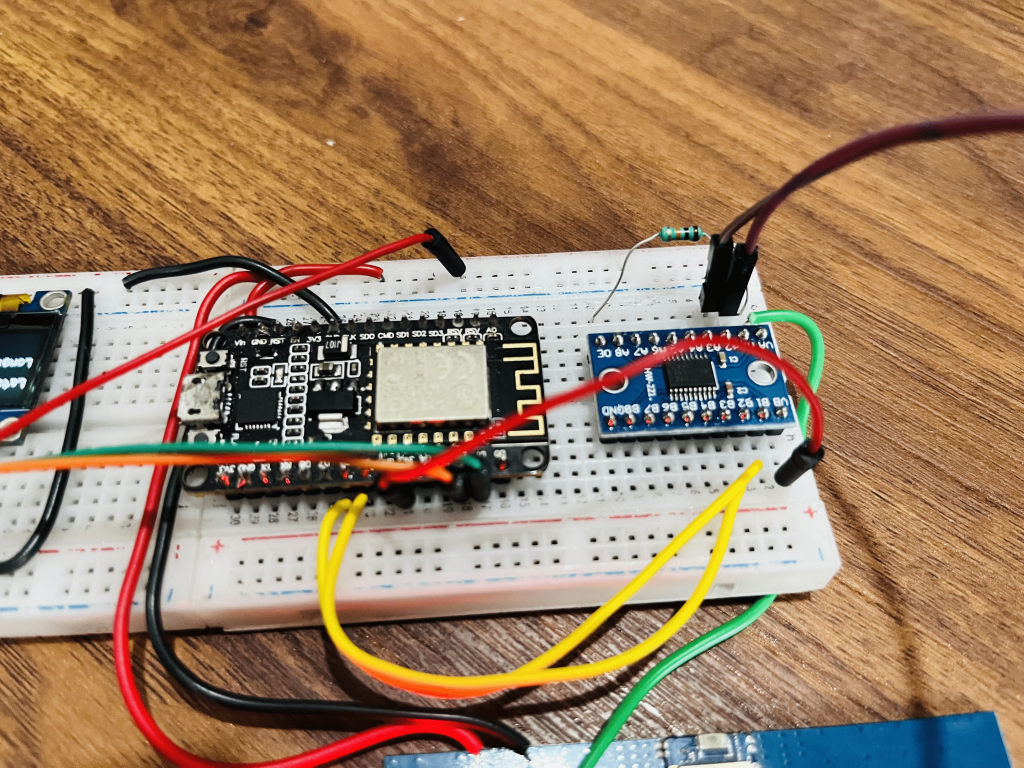
This EVB board already have 1.8v linear regulator, we can use the same to power up one side of logic convertor. Additionally, I removed some jumpers from the board to set the communication protocol to UART. All the info about the EVB board is shared in the datasheet provided by official vendor(RYS8830_EVB). A small OLED screen to display the co-ordinates interfaced via I2C bus to ESP8266.
The connection of RYS8830_EVB to NODEMCU:
Code for the ESP8266:
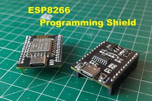
I have already explained in my previous tutorials to flash the code in NODEMCU using mobile app and Arduino IDE. You can see both the below given tutorials:
1) Program ESP8266 NODEMCU using Mobile Application
2) Program ESP8266 NODEMCU using Arduino IDE
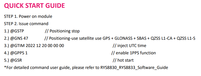
You can download the Tiny GPS, SSD1306 OLED from the manage library section under the tools menu in Arduino IDE. The same commands as listed above is executed by the ESP8266 to get the position info. Refer to the previous article to know more about GPGGA, GPRMC, HOT start and COLD start.
#include <TinyGPS++.h>
#include <SoftwareSerial.h>
static const int RXPin = D5, TXPin = D6;
static const uint32_t GPSBaud = 115200;
#include <Wire.h>
#include <Adafruit_GFX.h>
#include <Adafruit_SSD1306.h>
// The TinyGPS++ object
TinyGPSPlus gps;

// The serial connection to the GPS device
SoftwareSerial ss(RXPin, TXPin);
#define SCREEN_WIDTH 128 // OLED display width, in pixels
#define SCREEN_HEIGHT 64 // OLED display height, in pixels
Adafruit_SSD1306 display(SCREEN_WIDTH, SCREEN_HEIGHT, &Wire, -1);
void setup()
{
  Serial.begin(115200);
  ss.begin(GPSBaud);
ss.print("@GSTP\r\n");//positioning stop
  delay(500);
  ss.print("@GNS 47\r\n");// Positioning-use satellite use GPS + GLONASS + SBAS + QZSS L1-CA + QZSS L1-S
  delay(500);
 //ss.print("@GPPS 1\r\n");// enable 1PPS function
// delay(500);
  ss.print("@GSR\r\n");// hot start
  delay(2000);

  if(!display.begin(SSD1306_SWITCHCAPVCC, 0x3C)) { // Address 0x3D for 128x64
    Serial.println(F("SSD1306 allocation failed"));
    for(;;);
  }
  delay(2000);

}

void loop()
{
  // This sketch displays information every time a new sentence is correctly encoded.
  while (ss.available() > 0)
    if (gps.encode(ss.read()))
      displayInfo();

  if (millis() > 5000 && gps.charsProcessed() < 10)
  {
    Serial.println(F("No GPS detected: check wiring."));
    while...
Read more »
 ElectroBoy
 Waldo Wolmarans
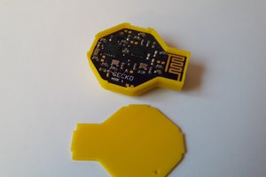
 Max.K
Max.K
 Hulk
Hulk