 Peter Sinclair
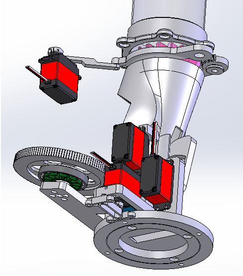
Now with CAD & CODE: https://github.com/TheSinc/BadmintonAce/
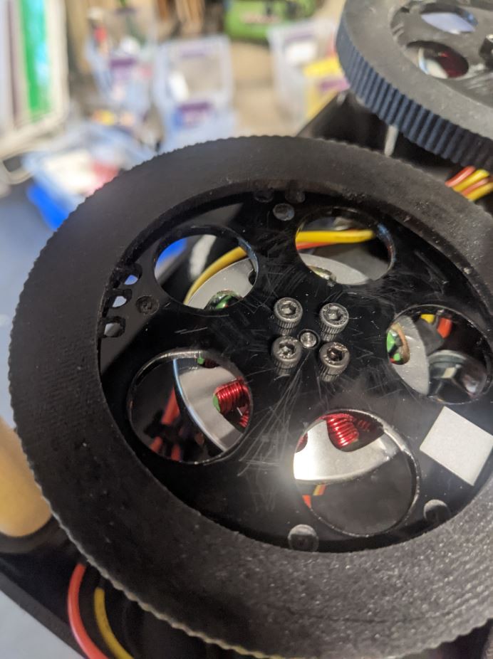
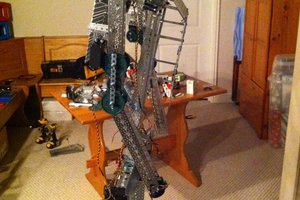
First few test feeds from the brand new hardware & software. Software is only roughed in enough to do some feeding so I could make a video but I like where things are headed. A long way to go to get the hardware and software completed and to place shots accurately & repeatable. See project log for more details.
Project Purpose & Social Impact
While this project started as a personal project to improve my own badminton skills it quickly became clear that it was much more. The excitement from children and adults alike testing early prototypes has been incredible. This project seeks to share that excitement with the world and to provide an engaging tool for physical activity, badminton skill building, and STEM education. As a complete mechatronics system it has something for everyone.
Teaching Badminton
One of the best ways for students to learn new skills is through shot repetition carried out using feeding exercises where the shuttle is 'fed' to the student in a specific pattern for them to return. While most coaches are excellent feeders, in larger classes students must often feed each other but they may not be able to do so consistently. This can impede their ability to learn the new skill. Lack of good feeding is particularly relevant for kids' classes where student feeding is not possible. An automated feeder solves these issues.
Learning Badminton
Learning badminton can be incredibly rewarding but it's not always possible to find a training facility that meets your schedule and budget. Coaching can be quite expensive and intimidating with many clubs geared to highly competitive players. With the Badminton Ace you can train at your own level and on your own schedule, using your personal badminton feeder along with the amazing content on YouTube and other online sources.
Learning STEM
While the concept of a launcher seems quite simple, the end product is a fully functioning robot. With many different sensors, motors, and techniques involved in the build it's a great opportunity to explore how it all works. In time, the detailed logs will highlight many of the design choices along with urethane molding, inverse kinematics, assembly, and programming. For those that just want to stick to badminton that deep dive is optional.
Improving Fitness
According to the World Health organization, worldwide obesity has tripled since 1975 and is growing at an alarming rate in children. Since regular physical activity can help prevent obesity and improve overall health it's important to find enjoyable activities. This launcher can help the user to improve their badminton skills to further their enjoyment on court while providing good exercise. Additionally, it can encourage a user, who might not be comfortable in public, to practice on their own to build confidence. More aggressive or random pattern options make for a great workout at any fitness level.
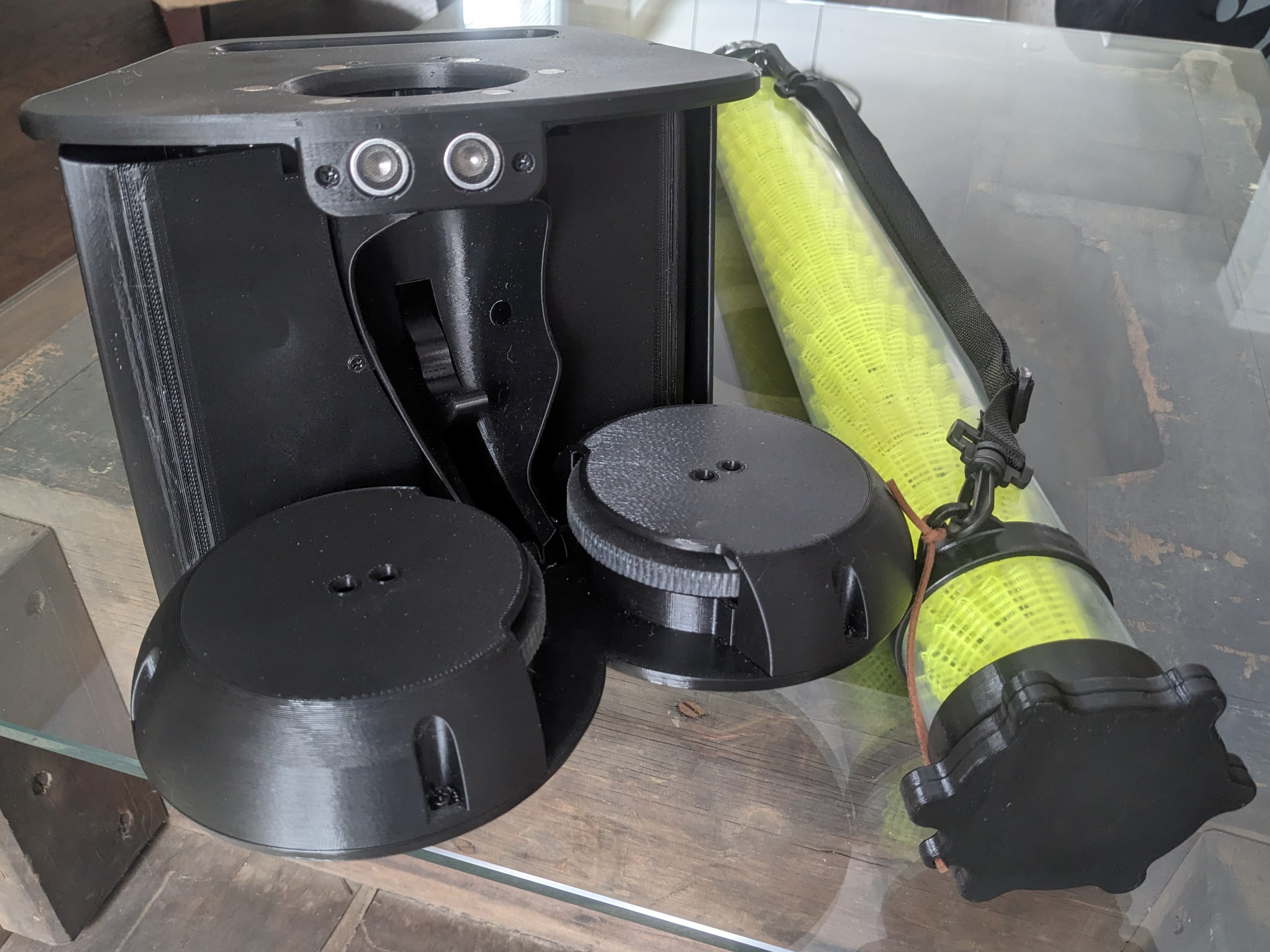
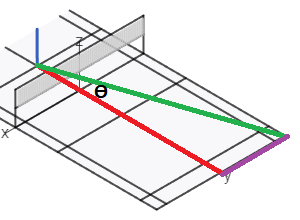
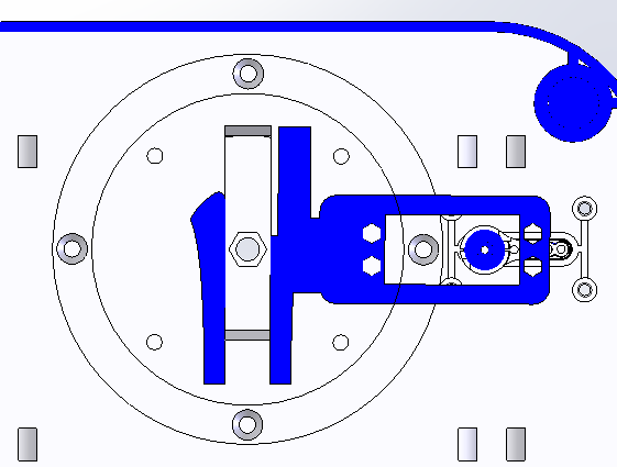
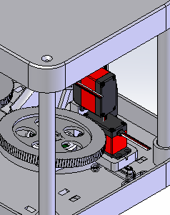
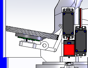
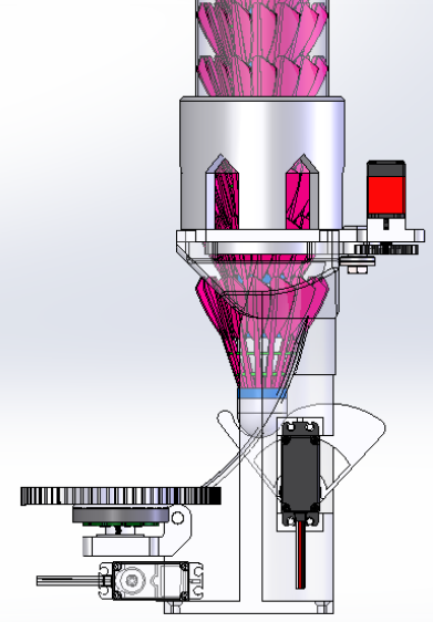
Theory of Operation
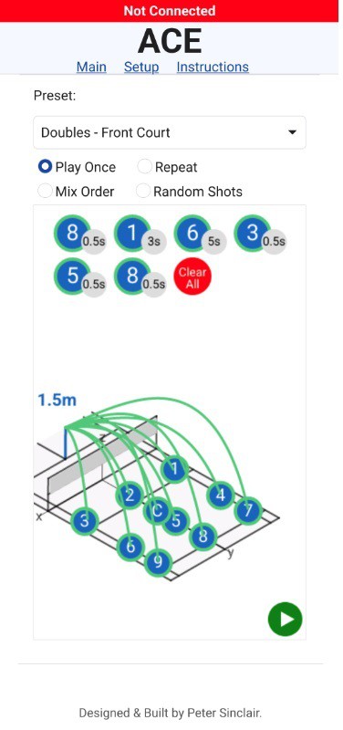
Badminton shuttles are placed in a long tube, acting as a supply magazine, which attaches to the top of ACE using magnets (making travel & refills more convenient). Once placed on the launcher, gravity pulls the shuttles down into the launcher where their movement is blocked using a servo controlled pincer gripper. The gripper opens which allows the shuttle stack to fall onto the catch/push arm. The gripper assembly then closes to hold the shuttle second from the bottom of the stack. The catch/push arm is then free to push the bottom shuttle into the firing wheels. Before this occurs, the rotation of the launcher and trajectory of the shot are set using two additional servos and the feed wheels ramp up to the desired speed based on the shot. The catch/push arm pushes the shuttle into the wheels where it is launched, then the feed motors shut off, and the catch/push arm returns to the catch position for the next shuttle priming sequence. The precise shot parameters & pattern...
Read more »
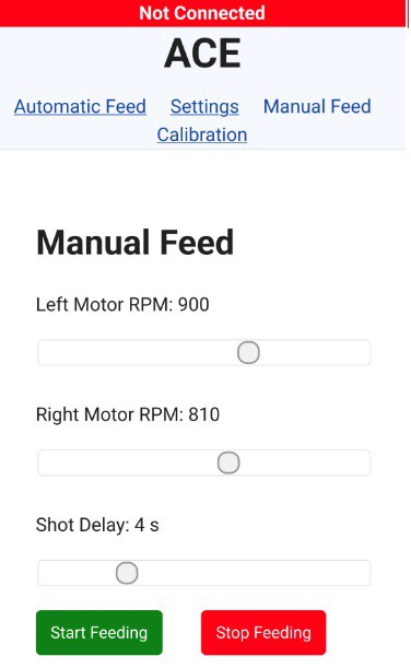
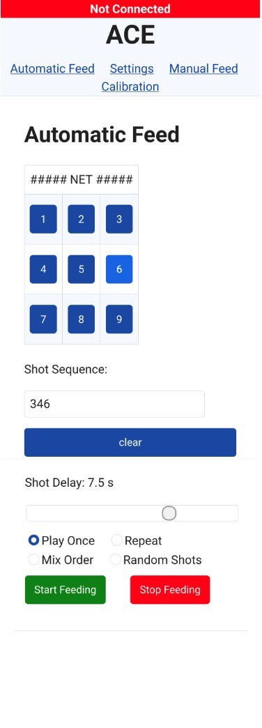 Automatic Feed


 Anthrobotics
 Kristjan Berce
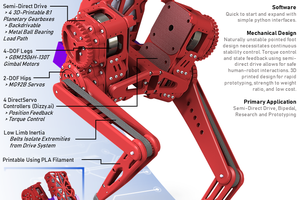
 Darren V Levine
 ThunderSqueak
Hi, I´m really glad someone took on the idea of the now dead Baddy project and even improved it. When I first read about Baddy I tried to order a set but I was already too late. Your design is really convincing. I´m not sure you still read the comments on this page but I would also appreciate some information on the electronics. I understand it´s a lot of work to get such information into a presentable shape for others to follow the instructions but even a few sketches would help here. 3D printing and mechanical assembly shouldn´t be a problem. For the wiring I just need more information to be able to reproduce your feeder. Concerining the BADDY I found the following information about the motors:
Brushless motors on the Baddy were around 730-850kv depending on which iteration. So the 750kv in this project shouldn´t be under dimensioned