0%
0%
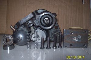
Japan Servo Co. Brushless motor from inside
just disassembling
Become a Hackaday.io member
Already have an account? Log in.
Just one more thing
To make the experience fit your profile, pick a username and tell us what interests you.
Pick an awesome username
hackaday.io/
Your profile's URL: hackaday.io/username. Max 25 alphanumeric characters.
Pick a few interests
Projects that share your interests
People that share your interests


 Arduino KIT
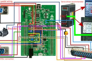
 Huang Jin
 salim BGZ
If my following assumption holds this is actually a very smart sensor design that they implemented here.
To drive a 3 phase motor you can use sensor-less or sensor based driving modes. The first uses back-EMF sensing to recover the encoder ticks from free running winding voltages crossing VCC/2 - while the latter has the hall switches positioned properly to obtain switching phase time points.
Sensorless drive is the most ill-defined in terms of servo control, followed by the sensor based drive. Consider however that you only get a hall sensor transition every pi/3 ( 60° electrical phase; the associated angle of rotation is 360° * (2 * 3~) / 12 poles for a full electrical cycle) so you'll have to interpolate position, speed and acceleration in between encoder pulses.
Expensive servo drives have high resolution encoders to get the most real-time motion signal but with a bit of trickery in software you can combine the hall sensor signals and a synchronous tacho signal to get higher resolution.
Thus my educated guess is that the squiggly trace forms an auxilliary sense / tacho winding which uses the sharp transition of the rotor magnetization profile (the poles will have well defined magnetization boundaries owed to their aspect ratio) to detect a higher harmonic of the rotor field to derive the tacho signal.
You'll also note that the pitch of the sense trace loops is such that it is not in sync with the stator poles, e.g. it ought to be something odd like 4.333(3) sense loops per pole to keep in sync with the rotor field. There are more/less rotor poles than there are stator poles - in my example it's 14 rotor to 12 stator poles and 52 tacho loop periods. You'll have a better chance at counting them as I can judge from the pictures.
The coolest thing in this design is that the sense winding and thus the tacho signal - is free.
Ultimate test: hook up a scope and measure the waveforms and frequencies of a drive winding vs. sense winding.
I found this great illustration which I stole from the internet for educational purposes: