 Arya
AryaThe phone has to have plenty of hardware both on front and back, as well as some on the sides. Usually, the keypad phone designers built a phone with one big mainboard (as big as the phone itself) often a separate flex PCBs for keypad/side keys (occasionaly using mechanical side keys). In flip phones, there'd be another PCB for the LCD panel most of the time.
How do I know? I spent 4 years fixing mobile phones (also PCs and laptops) for a living, and I used to repair my own phones before that. I didn't exactly design those, and the repairs would be "replace that module" most of the time, but it gave me insights into what components they typically use and how they're put together.
Dimensions
Two months ago I started making mockups out of paper so that I'd have some insight into what the boards should look like. It was clear there'd have to be at least 2 PCBs - one for the front and another one for the back. I wouldn't be able to make the thing smaller than the Pi Zero,and making it slightly wider wouldn't be such a big of a problem. Pi Zero is 31mm wide, I just rounded it up and got 40, which looked perfectly fine.
I was going to order the PCBs from DirtyPCBs, and as I couldn't realistically aim for 5x5cm panel, I chose 10x10cm. Then I measured the keypad layout I was aiming for, the display height and understood that it'd be close to 10cm height, so I might as well make it 10.
Keypad
Now, when I was sure the thing would need to be a PCB sandwich, and I knew the dimensions. I made a list of features for the front panel. After much planning, I had to add a MCU for the keypad, which adds a step to the assembly. then, I understood that routing the keypad traces on the same PCB as the MCU, ESP-12 and Pi Zero headers wouldn't be as comfortable to do as it looked like, so I opted to make the keypad a separate layer. Is it still possible to route it on the same PCB? Yes. Would it be possible to make it as quickly as I did? Doubt it.
However, if there'll be a significant demand in making the phone thinner, it should be possible to route it all on one PCB. Not only thickness comes into play - the front and back PCBs will be able to fit on one 10x10 panel, which is a 50% off PCB manufacturing costs if you're assembling it yourself!
Inter-PCB connections
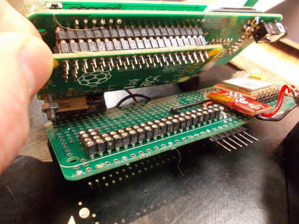
It turns out 2.54 headers are a cheap and solderable solution that works well. You can use a single 2x20 header to connect all three boards, a couple of headers to atach keypad PCB to the front PCB and some more headers for the GSM module. When I was designing a board, I knew I'd need to make a KiCad Pi Zero part. I added 2x20 2.54-spaced plated-through header, but didn't pay attention to the fact that the plated-holes wouldn't have enough width for a typical 2.54 header. When I got the boards, I was initially disappointed but then understood it's actually possible to make it all fit - just press the connectors in a little. Moreover, the boards are held together without soldering them (with the exception of Pi Zero itself) - it doesn't mean it makes a secure connection electrically, but it makes it all easier to be soldered together.
Furthermore, using 2.54 headers means that I can use machined headers to make a phone that's thicker, but can be easily assembled and disassembled. I assembled a prototype that way, and it works quite well, though I need to use hot glue to hold the back PCB and Pi Zero together. Also, when using machined headers, I need to add a screw with 3 to hold the boards together because otherwise pressing on the keyboard makes the whole setup bend enough to disconnect the machined headers (it's better on a prototype with soldered headers).
The downside of using simple pin headers is that, in order for the phone to be disassembled, you have to desolder 40 (best case - 25) 2.54 header pins from both sides. That's very uncomfortable to do, and I'm ashamed to state I don't yet have a solution for easy disassembly. I hope I'll find a way to still allow easy disassembly, or at least work around this as efficiently as possible.
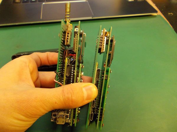
When I look at the prototype I'm using now, it consists of 9 (nine PCBs):
- The Pi Zero in the middle
- The front PCB
- The display breakout PCB (soldered to front PCB)
- The keypad PCB with all the keys
- The ESP-12 module (which is just a black PCB with ESP8266 chip, SPI flash and antenna on it, covered with a shield)
- The Li-Ion charger PCB (harvested from a powerbank, using some SOT 5-pin IC for charging) (won't be in final version)
- The back PCB
- The Li-Ion fuel gauge PCB (for logging the battery life of this prototype, uses MAX17043) (won't be in final version)
- The SIM800 breakout PCB
While that count can be decreased (I'm not smart enough to predict the mechanical stability of this), it makes for easy assembly and easy sourcing of the parts. Moreover, using off-the-shelf display breakouts means you'l be able to use another display if necessary - but that's a topic one of the next hardware/design decision writeups!
Discussions
Become a Hackaday.io Member
Create an account to leave a comment. Already have an account? Log In.
Just for reference, seeedstudio has now 100x100mm PCB of any color for 9,99USD+postage, something like 14USD total.
Are you sure? yes | no
Hmm, will try it out this time! Last time was DirtyPCBs and Elecrow, this time I can easily pick a different board house if the tolerances are right.
Are you sure? yes | no
Don't worry, quality wise - the PCBs from those producers are all similar. I mean very similar.
Are you sure? yes | no
Just checked and it seems they have a "multiple design on one order" penalty - see for yourself: http://support.seeedstudio.com/knowledgebase/articles/388503-what-are-the-pcb-panelization-rules . The price literally doubles for two different boards, that sucks a lot and is not suitable for ZeroPhone at least.
Are you sure? yes | no
be clever about the submitted-layout and get out your tin-snips ;)
Are you sure? yes | no