 Arya
Arya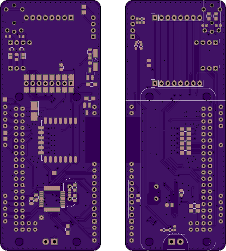
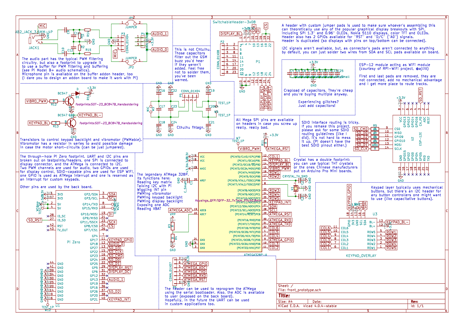
New revision of front PCB was developed. It's hopefully final for now (Murphy's laws still apply). I've changed a lot of things, such as component placement, ATMega pin usage and audio connections. with a PCB like this, it's "solder components and it works", just like it's supposed to be. This Monday, front PCB was just sent to OSHPark (and I want to express my gratitude to @oshpark for giving us a discount, the project can now move forward much faster!). Also, props to @jaromir.sukuba for reviewing the boards and suggesting many useful changes!
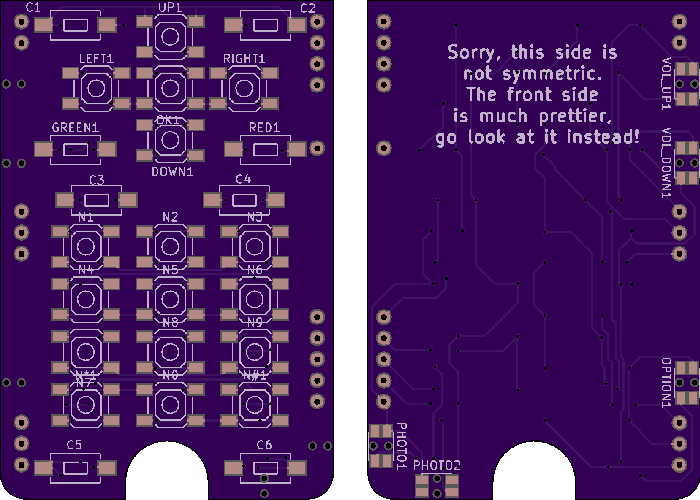
The keypad PCB got new features! First of all, I erased all traces and let my OCD take over. As a result, the front side has fully symmetrical traces (once you solder the keys on, the board is supposed to be beautiful). @Lars R. suggested capacitative buttons. I'm not going to make that myself (I like mechanical switches), but I made sure that whoever wants them can add them - keypad now has I2C lines coming from the Pi (as well as power and one GPIO for interrupts). Now anybody can just design another keypad PCB with a capacitative button controller. Keys were moved and made easier to solder, too. Also, there are two side button options on eBay - I made sure keypad PCB supports both.
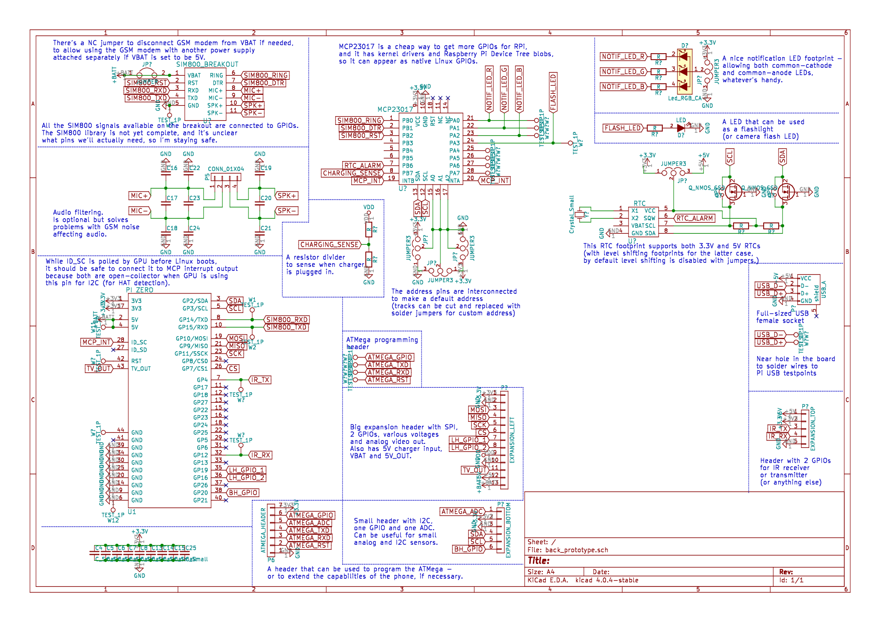
The back PCB is not as simple - it's still work in progress. I forgot that it needs all the power management stuff, like RTC with battery, 5V generation for USB (still using available components), a full-sized USB socket (placed in a non-weird way) and have access to Pi USB lines. Hey, let's talk about the back board!
Back board:
DONEs:
- I decided to bring out all available GPIOs to expansion headers on sides of the phone, to female headers. They're grouped and positioned based on how they're commonly used, the most logical way I've found. I even have included the TV out signal on one of the headers, hope somebody can make use of that.
- I had to add a MCP23017 GPIO expander. The phone's out of GPIOs with all the interfaces taken, and I needed some management functions. Good news - it should be supported by Linux drivers, so it actually creates Linux native GPIOs and we don't need another daemon running exclusively to work with this I2C device.
- I added an RGB notification LED - a feature I missed so much from Nokia times, something that modern phones have scrapped (for what, 0.02$ in BOM?). It's kinda bulky at the moment, supporting THT RGB LEDs, but I plan to add an SMD footprint in parallel.
- I also added a single large LED (again, idea courtesy of @Lars R.)! Could be used for camera, notifications, as a flashlight or whatever else you can imagine - maybe IR backlight for night vision.
- I understood there better be an RTC - with all the features a phone like this should have, proper timekeeping is something absolutely necessary. The footprint I've added is quite generic - many RTCs will fit. As a last resort feature, there's a possibility to use older 5V RTCs - there's even level shifting components added (jumpered until somebody really needs them). Unfortunately, the SIM800 RTC battery pin is not available on the breakout used =(
TODOs:
- Making the footprints for GSM modem breakout, DC-DC breakouts found on eBay and TP4056 breakouts
- Choosing a RTC battery (and a holder)
- Figuring out the component positioning - I've already planned out the expansion header positions. Battery connector, USB socket, battery itself? Not so much, all limitations apply. Add the modem, RTC, DC-DC and expansion header labels, and it quickly starts to get tricky - not to mention the modem for 3G/4G is likely to be much bigger (and take USB?)
All of that till Monday - I want to speed up the prototyping stage, that means I have to send off the back PCB to OSHpark on Monday.
I think I'm done with articles for today - I liked the way I annotated back PCB schematic while drawing it, I think I should go do the same with the front PCB!
EDIT: Done!
Discussions
Become a Hackaday.io Member
Create an account to leave a comment. Already have an account? Log In.
Exciting! We look forward to seeing future updates
Are you sure? yes | no