 Arya
AryaAs I mentioned earlier, ZeroPhone is basically a PCB sandwich. Now, ZeroPhone consists of three custom boards, a Pi Zero and 5 Chinese breakouts:
- ESP-12 board
- SIM800-based modem board
- 1.3" OLED breakout
- Li-Ion charging circuit
- Step-up DC-DC board (generates 5V for USB port)
All of these boards, except (very popular) ESP-12 breakouts, can change. Reasons are - Chinese optimize those breakouts all the time (decreasing BOM count and/or PCB size), want to add features to innovate (consequently, to raise price), and, I think, sometimes just copy the pinouts and board outlines from one another, re-tracing the board.
For example, here are photos of different Arduino Pro Mini clone PCBs I have:
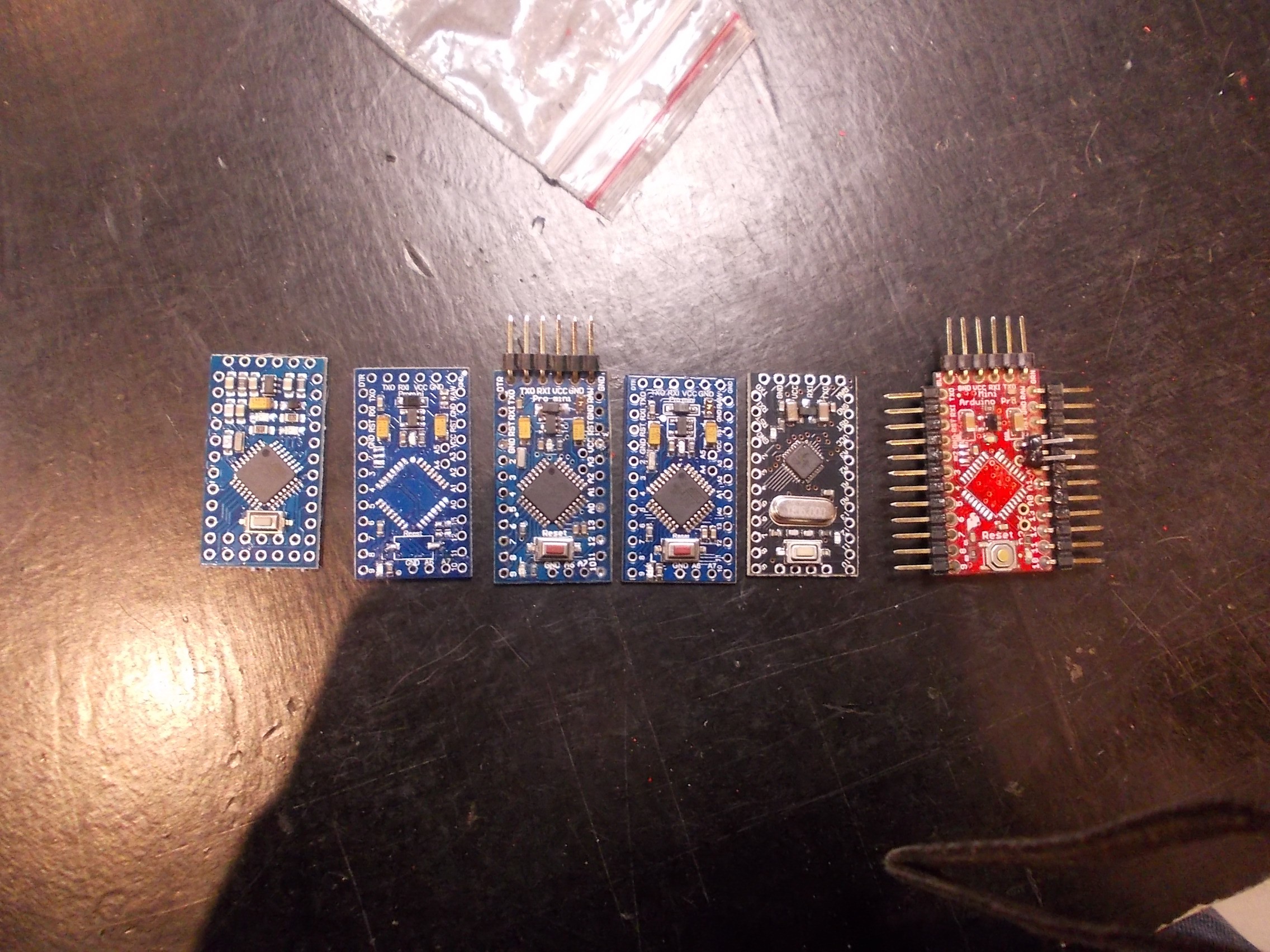
Some of them don't look different, but the traces are all routed differently, and some differences are easy to spot from this photo - such as holes changing places. And that's only what I have currently, I've used and seen much more different boards.
They went through these revisions in a couple of years, and it was mostly moving components around, but pinouts also changed - mostly A4-A7 pins. If you're designing a shield for Pro Minis (for easier assembly and user-friendliness) and it uses I2C, tough luck with sourcing boards.
I'm assembling a batch of 20 prototypes now, as you can rememember, and I got the components for them. However, those components weren't what I expected.
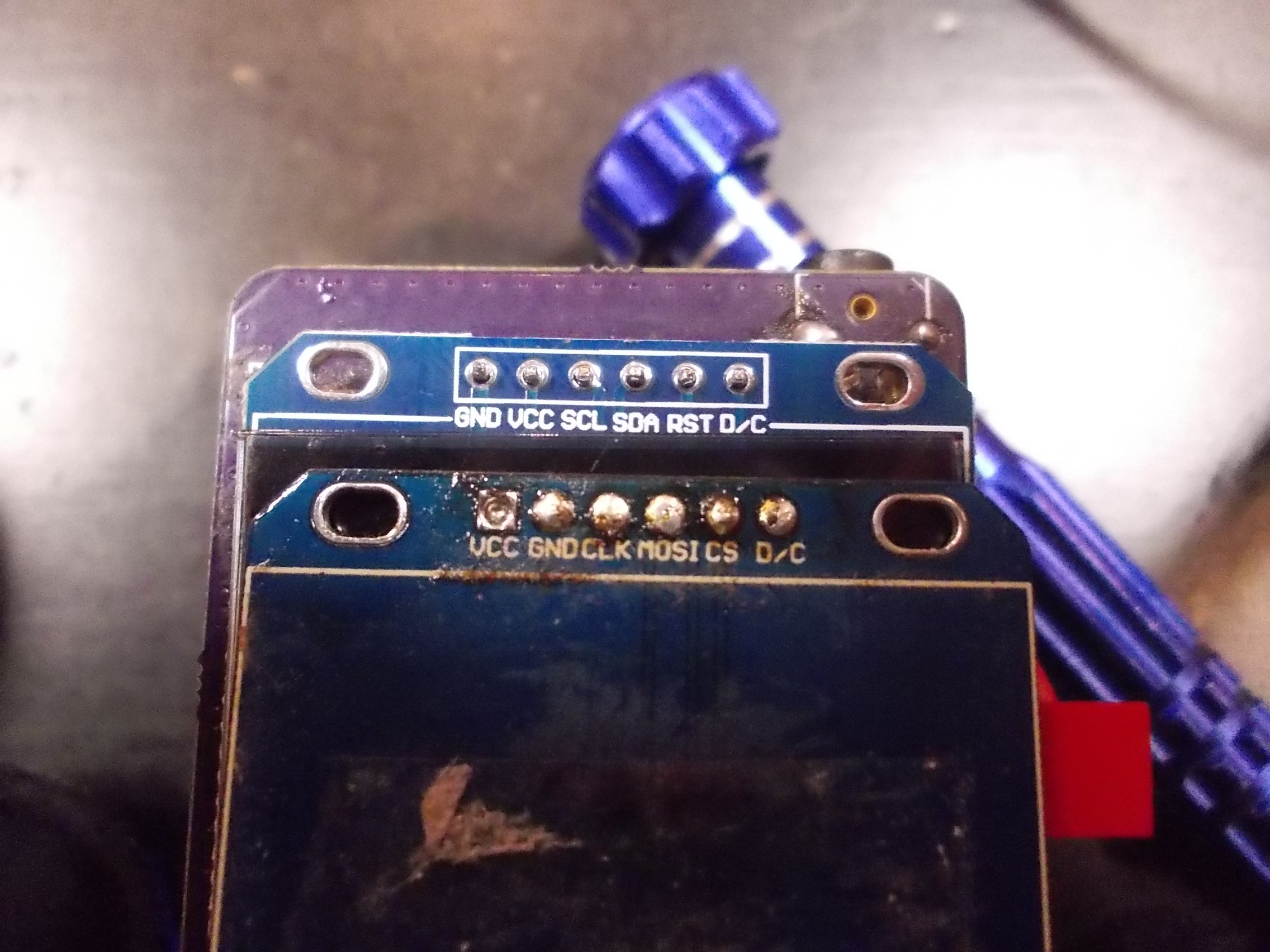
Check out those two screens. The pinout changed, and in a bad way - the first display I connected just burned out because GND and VCC were swapped (I'm glad that SPI survived). However, this is not the problem - my multiple-pinout header takes care of that. The largest problem is lack of CS pin. It means that the SPI bus can't really be shared between the screen and the expansion header - the expansion header that's supposed to work with ZeroPhone addons. The other displays I've been using are all OK, and I'm sure that if I bought other displays, they wouldn't have been as braindead. To be honest, I should have looked more closely at the display breakout the Chinese seller listed - it does show the pinout on the photo. =(
Seems like that lack of CS pin is only the problem for the *cheapest* breakouts out there. Seems like somebody made quite a bunch of them, and now is trying to sell them as cheaply as possible - multiple TaoBao sellers have those.
Talking about this small batch, there's certainly a way to fix the display breakout - however, I still haven't found it. Whatever the fix is, it's going to involve some manual work with the PCB - not meant for production, and, as the fixes I've attempted so far have failed, I'm going to need to experiment with it tomorrow.
What more, the LiIon charger breakouts I got are also screwed up.
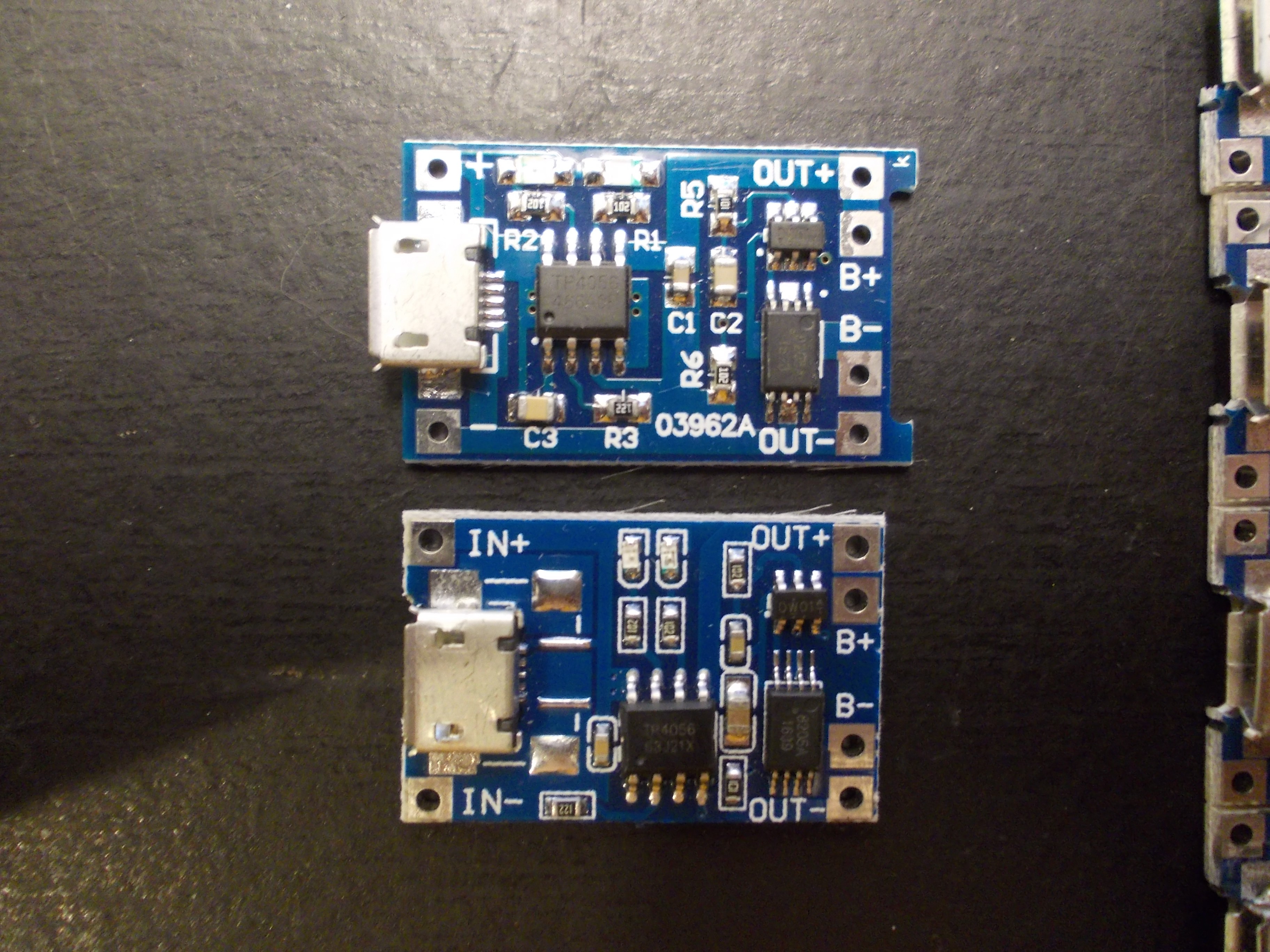
Top breakout is the "normal" breakout I've been using for years now. Bottom breakout is the one I got from TaoBao. It does take less PCB space, yeah, but the MicroUSB connector is shifted in a way that wouldn't fit on normal boards .
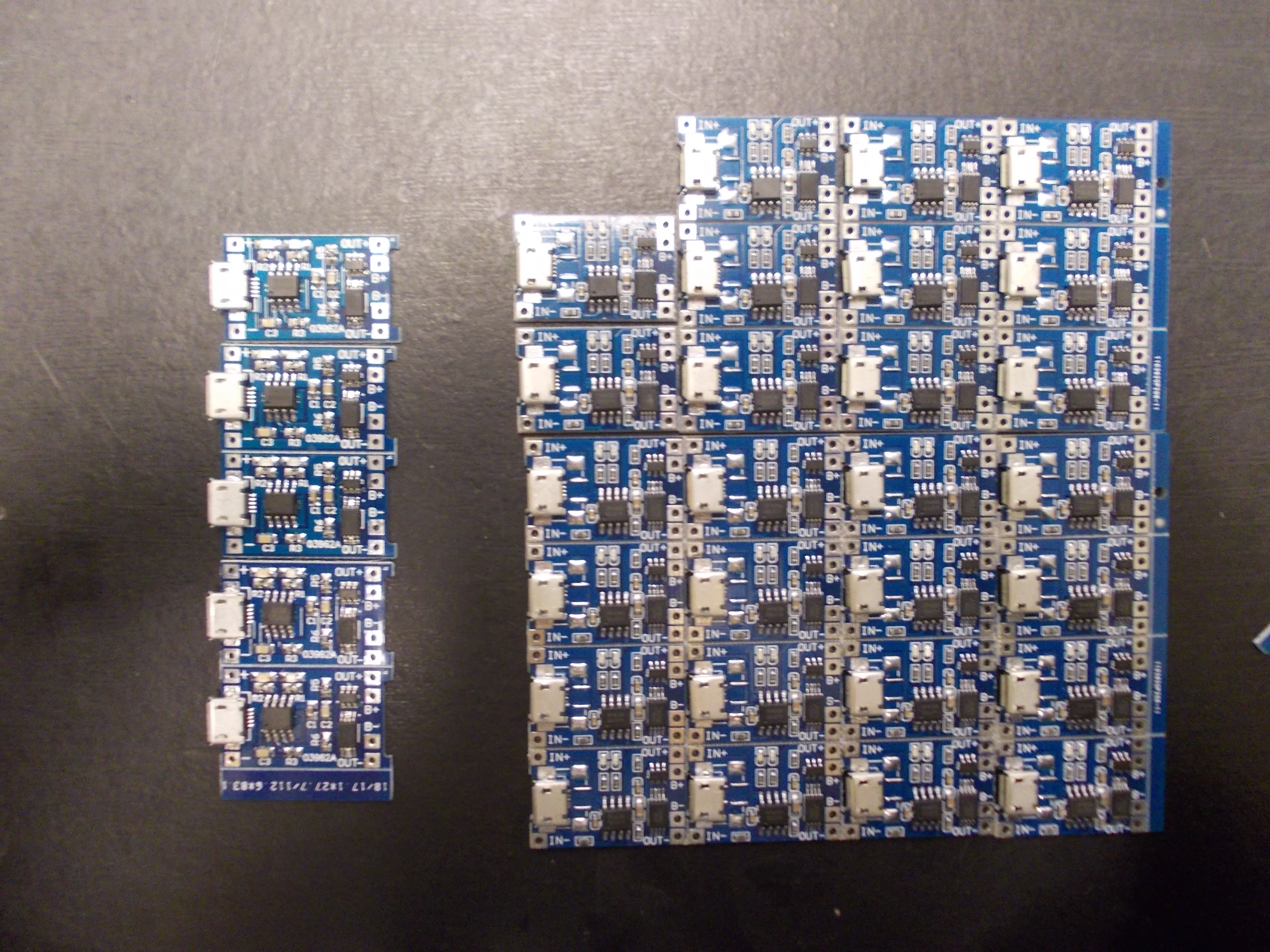
How many "normal" breakouts I have, vs how many "screwed" breakouts I have
I haven't had ordered the gamma boards at the time when I received the breakouts, so I quickly made a redesign of the gamma boards - I thought I couldn't really risk ordering more breakouts and receiving the screwed-up ones again. Now I think I was mistaken - I should have ordered the normal boards from eBay once again, two-three weeks from the moment I got the breakouts wouldn't be that unreasonable, since I would have had gotten them the beginning of this week. What more, I think I'll have to revert the changes - I had to move the breakout footprint on the Gamma boards, as a result, it's now mostly compatible with those changed boards - not so much with the "normal" boards, they stick out of the outline =( However, what if I revert the changes and then the "normal" breakout will fade away from Chinese sellers?
To sum up, the charger boards are not as much of a PITA as display boards are, and Gamma ZeroPhone assembly won't be interrupted by those - but I'll need to revert the changes and avoid using these breakouts again.
I've been told about this kind of problem before. The reason I'm now bringing it up because it started affecting ZeroPhone, and we need to do something about it. I'll be thinking and researching about ways on how to avoid it when producing ZeroPhones, and for now my lesson is "Be very careful when ordering breakouts". I should also refrain from doing quick changes to boards - I think that I should make sure the breakouts *actually won't be available anymore* before adapting the boards to a new version of breakouts (unless I'm forking the boards for a side project, then anything goes).
Production-optimized ZeroPhones
One more important idea I'll be working on is production-optimized ZeroPhones. The hacker-friendly PCBs are here to stay and will be maintained and upgraded, but not everybody actually needs hardware-hacker-friendliness. What's are the differences for the production-optimized version?
- 4-layer boards - with proper power planes and better routing possibilities
- Smaller SMD packages - for both chips and passives (still using parts that can be easily sourced)
- Using OLED panels, ICs, SMD GSM modules and connectors instead of relying on breakouts
- Possibly, merging the keypad and front boards
As a result, the production-optimized version will have considerably less risks associated with its production, availability of components and possible mistakes that can be made during production. It will still have extension ports, full software compatibility and be open-source hardware, of course!
This could help make ZeroPhones cheaper, smaller and less power-consuming, as well as somewhat more capable. This could open ZeroPhone to a huge market of people who just want a Linux smartphone but don't want to work with hardware (many survey responses talk about this), and it would make the ZeroPhone much more reliable for those people.
More importantly, it makes manufacturing much, much less error-prone, and this is a very important factor that will help once I take responsibility for manufacturing ZeroPhones in more or less large quantities. I'll still be crowdfunding the hacker-friendly version this year, but it's possible I'll start crowdfunding of production-optimized ZeroPhones by the end of 2017. I'll further outline production-ready ZeroPhone version here before I start working on it, so stay tuned =)
As always, will be glad to hear your thoughts in comments/over email!
Discussions
Become a Hackaday.io Member
Create an account to leave a comment. Already have an account? Log In.
I guess the usual way you work around those kind of problems is to put everything on your own PCBs. That's what you want to do for any bigger production runs anyways -- because it will be much cheaper and easier to assemble on the production line.
The second best way (I think) is to find trusted sellers and order from them -- that's what I did with Tote. Of course, there is also a certain engineering challenge in coming up with universal footprints that fit any variation of the module -- but it's a losing battle, as they will always come up with something you didn't anticipate.
Are you sure? yes | no