 Arya
AryaThis project interests many people. Many people asked questions and gave suggestions, some went as far as to contribute. Those people are interested to help me with various aspects of the project, and most of them will need hardware. So, I had to learn to assemble, test and ship things =) Assembly is simple, shipping is, too. Let's talk about testing the boards.
The boards go through e-test on the factory - to check for shorted or disconnected tracks. However, I still had to ship every board with an ATMega programmed, two traces cut and 5 magnet wires soldered to make new tracks. Furthermore, I literally emptied all my Arduino Pro Mini stash by this time and had to re-use ATMegas from Pro Mini boards harvested from my previous projects - some of them definitely had fried GPIOs, I just couldn't tell which ones. Also, same could be said about my ESP-12 module stash, I had to check every one I could harvest from somewhere, since I burned some of them - been recklessly driving motors and doing other horrible things with those.

Thankfully, my hackerspace has a stash of pogopins - hard lessons learned after one of the members had to make a testing jig urgently, then had to pay 1$/pin from Farnell. Next best thing was that all the pads with necessary signals were through-hole. What that meant was I could just use the drill file from Gerber files and not export copper layers (like I would have to if I needed pogo-pins on some SMD pads). The workflow for me was as follows:
- Take the Gerber, open it in KiCad's Gerbv, deselect anything but outline and drill files
- Export it to SVG
- In Inkscape, remove unnnecessary holes, make uniform line thicknesses, adjust the hole sizes (so that pogopins would fit just right and not be loose)
- Export it to the hackerspace's laser cutter
- Cut, check, fix, repeat
Spoiler: three screws weren't enough, it'd bend.
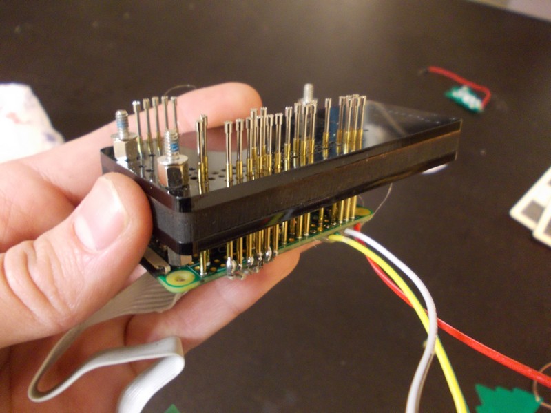
In the end, I got a nice laser-cut pogopin holder in shape of the boards, made as an acrylic-wood-acrylic sandwich (you can already tell I love things made from layers) and inserted all the pogopins (only those necessary for testing ATMegas/ESPs). Then:
- I soldered a spare Pi Zero to the Pi Zero socket pogopins - it was easy. Just align pogopins with the Zero socket and fill the Zero's holes with solder from the other side - solder will flow onto the pogopins, connecting them with the necessary pads.
- I soldered a spare ZeroPhone keypad I had to the keypad row/column pad pogopins, using a flat cable made from an old cable with connectors cut off
- I made sure that the board would not bend while only being held by screws in three points (and being pressed on by pogopins) - I had to add a makeshift clamp to prevent the board from bending.
- I added 4 wires for power/UART - UART being the most reasonable connection in this case, it allowed me to see the kernel debug output, access the console and easily solve problems if things went wrong.
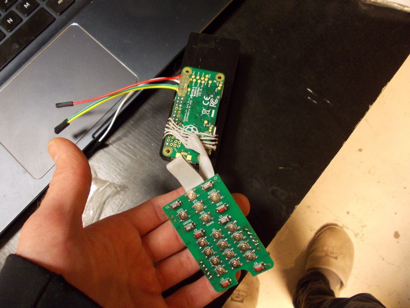
Keypad board, UART connection and the poor Pi Zero
Out of 5 boards I assembled, I had 4 with ATMega problems and had to replace those ATMegas - very lucky I tested them (the 5th one had loose wires I had to resolder). It was harder to test ESPs (they were working with interruptions, probably due to wire length), but it was quite simple - both ESPs I had initially just heated up, so the trash bin they went and I managed to find some working ones by calling a couple of friends. So far, it's been a good preparation to what I'll eventually need to do - test the ZeroPhones I'll make for sale!
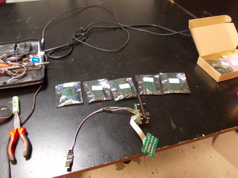
First batch of ZeroPhone alpha units - tested and going to contributors
I swear, one ESP-12 module I had just disappeared somewhere. ESP-12, if you happen to be reading this - I need you here. Come back ;'-(
Discussions
Become a Hackaday.io Member
Create an account to leave a comment. Already have an account? Log In.