 Arya
AryaI got this beautiful board in the mail yesterday, put it in my pocket and forgot about it till I needed something from that pocket, about 20 hours later. Anti-static bags FTW, also, Zeros are small and this one is no exception.

Zero W 1.1, Zero 1.3 and back board of ZeroPhone Beta
This review is going to derive as much conclusions as possible from the PCB layout (comparing Zero W to a simple Zero), components, specs and datasheets - I don't even have enough components to assemble a Zero W-based ZeroPhone, never mind the time.
First of all, a closer look of the front - comparing the Zero W and the usual Zero.
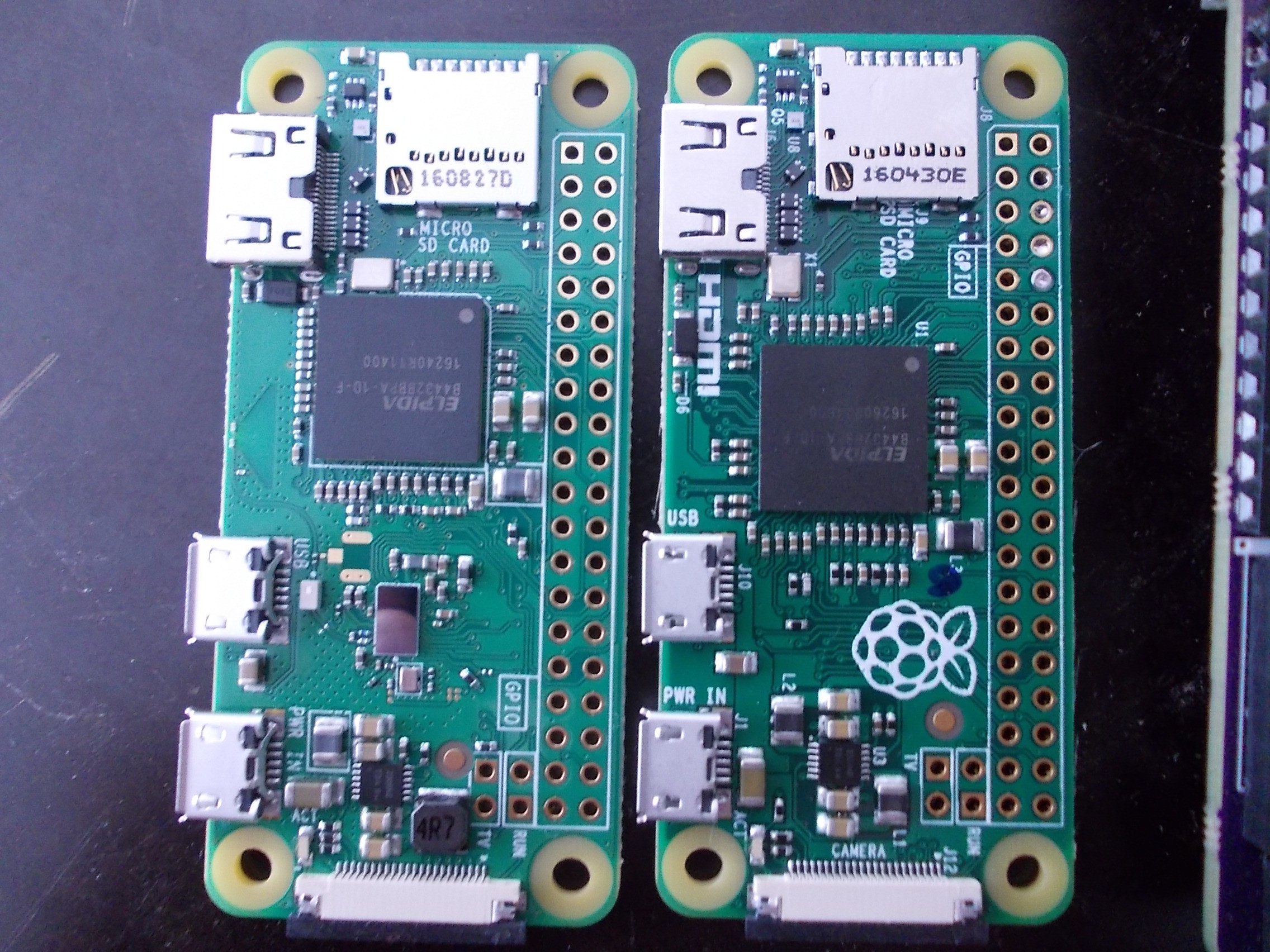
- Must have been quite an optimization, stuffing it all in. CPU had to move further up, SMPS part got more tightly-packed. Most traces are re-routed. Even though connectors stay in the same place, most SMTs have been moved (with exception of HDMI stuff, it seems). Traces have been completely re-routed, some even moved to other layers (looking at the GPIO area.)
- They even removed Raspberry Pi logo and component markings (why were they even necessary on this board? It's not OSHW anyway.) Even USB port markings ("USB" and "POWER") were moved, even though there was enough space. RF black magic-ish requirements (not too likely, the USB label isn't that far from the antenna anyway)? Simply lack of space? Hard to tell for me, a weird decision. "CAMERA" label simply disappeared, too, though that one is understandable (but it could have been moved to the bottom, at least - and it wasn't).
- RPF also changed inductor of the SMPS - apparently, to one capable of more current (it's 3.3V line inductor, in case you were wondering, I just checked).
- The u.FL connector could just be usable, but I should re-read the RPF statements - I recall hearing something about the fact that this antenna is as good as RPi3 one. Having an external antenna is generally good, but even the permanent mod is going to be hard - moving a 0402 (is this even 0402, or is it smaller?) is, well, tricky. As for this, I should go ask somebody what kind of antenna is this.
- A temporary mod like "a connector with a switch" would be hard to make, too. Depending on what part of the antenna trace actually works as an antenna, it could be from easy to impossible - it'd require cutting traces, anyway. I don't think we'll be getting monitoring mode with this one, too - when I last looked, it wasn't there.
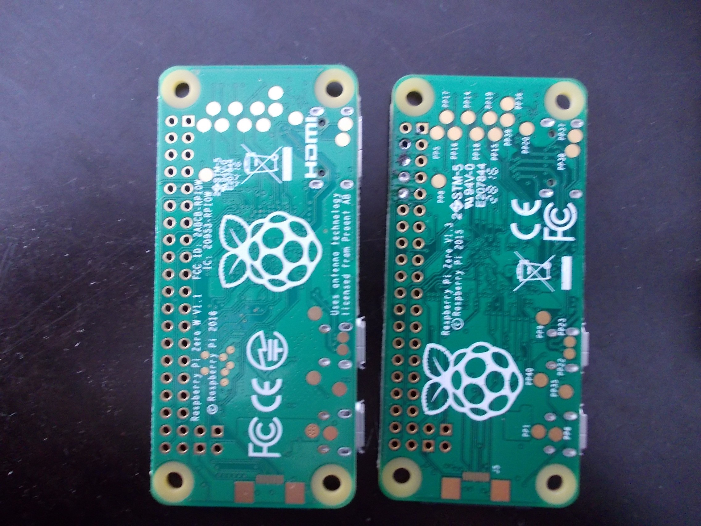
Zero W 1.1 and Zero 1.3 - back sides
- Testpoint markings disappeared from here, too. However, the placement didn't change - I assume it's so that they don't need new testing jigs (however, VC JTAG FPC socket did get repositioned slightly!)
- There are 7 new testpoints, the smaller ones on the W. Even though BT+WiFi take 8 pins, there are only 7 testpoints. I'm very, very curious, why there are only 7 and what GPIOs do those correspond to.
- The OTG_ID testpoint (PP40 on the right board, same palce on the left) trace was re-routed in a weird way - it goes away from the connector, then goes to another layer and comes back, to the USB socket. Most likely, it's because of that space full of vias that the antenna goes through (part of the antenna?)
- There's a disclaimer about who they got the antenna from - "Uses antenna technology licensed from Proant AB". Could have been part of the deal they had to make to get a lower price, who knows - anyway, it's a good advertisement for them, I should check their site sometime soon =D
- The board copyright marking says "2016".
The last part is interesting - two months between the "board designed" and "board available" seems to be quite a long time for me. I assume that FCC took quite some time, or, possibly, RPF wanted to make enough of the boards first. Also, maybe v1.0 was designed in 2016, v1.1 was made more recently but the copyright year wasn't updated, who knows =)
Impact of the changes
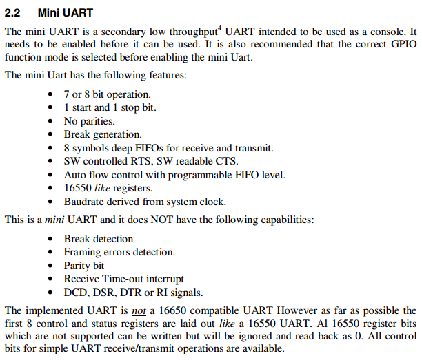
- As with the Pi 3, the UARTs have been swapped - Bluetooth gets the stable and high-performance UART, we get the MiniUART instead of the one we were used to. What does it mean? This:
![I don't know enough to explain the full meaning of this, though.]()
- It's going to consume more current. It's not going to be a problem with most Zeros connected to wall-warts out there, but might be a problem for the battery-powered projects, since we now need to make new power measurements. Also, does WiFi still have those stability problems in "power saving" mode?
- If you use a pHAT with a ground pour, it might negatively impact the antenna performance. In practice, you might not notice anything.
- If you have a case with a cutout for a CPU heatsink, it won't really fit - the CPU has moved.
What's the importance of this to the ZeroPhone project?
It's more good than bad news, in general.
- + We get Bluetooth - something that would have been hard to implement with just a Zero - UART is already occupied by GSM modem.
- + We free 6 pins - from the SDIO interface that ESP8266 used. We can then use those SDIO lines for something else, like, using SPI and getting additional UARTs through an SPI-to-UART chip, or using I2S.
- - There'll most likely need to be two different versions of boards, to accomodate the differences - the W version wouldn't need to have ESP8266, but could have something else instead. I'll have to think it over for at least a week. I'm already having problems with needing two different versions - one for 2G and one for 3G, this isn't any better.
- - The power consumption is yet unknown. If the WiFi+BT version would consume more current, all of the time, with no way to disable it in a way that lowers the current consumption to the same values that normal Zero has, that'd just suck, a lot.
- - MiniUART - ZeroPhone uses the UART for a GSM modem, and any stability problems are going to be a big problem for ZeroPhone, given it's supposed to be a phone, first and foremost. We could try and swap the UARTs (so we get normal GSM and so-so BT), but we can't do it fully - we can remap normal UART back to the GPIO header, but we can't remap the MiniUART to the Bluetooth, unfortunately (not without hardware mods, maybe the testpoints could be used). Hell, it's not even certain BT hardware (as well as driver) could use the MiniUART.
TODO:
- Power consumption measurements - compare to ESP8266-based solution (will be easier to do once I get the current sensor boards from DirtyPCBs)
- Determine those 7 testpoint purpose and GPIOs - maybe try toggling them from userspace?
- Plan out the GPIO alt functions for the next revisions of ZeroPhone - quite likely, for the version that comes out as a result of the crowdfunding (should the version that I'm developing now be called Gamma instead of v1.0?)
Discussions
Become a Hackaday.io Member
Create an account to leave a comment. Already have an account? Log In.
I grabbed one from Microcenter saturday but it didn't install when I booted it with NOOBs just hung up lol, need to try again later this week.
Are you sure? yes | no
"We free 6 pins - from the SDIO interface that ESP8266 used. We can then use those SDIO lines for something else, like, using SPI and getting additional UARTs through an SPI-to-UART chip, or using I2S."
- I'm a bit confused, the SPI port itself is on other pins than the SDIO, isn't it?
Are you sure? yes | no
Oh, sorry for the wording - I don't have this part so well planned, either =) But the essence is - there are interrupt and general-purposed GPIOs which currently occupy the pins that could be mapped to SPI. Those pins could be moved to the pins that were occupied by SDIO, so that we could free up SPI, and/or I2S, which is indeed on the SDIO pins. It's going to be a tricky change anyway, keeping compatibility with things and all that - I will likely work on it tomorrow.
Are you sure? yes | no
ahhh, I see :)
Are you sure? yes | no