 Arya
AryaOne more iteration of hardware - I wish I could say it's the v1.0, but I made enough changes to know there will certainly be bugs. Therefore, it's a Gamma revision - this is the revision that's going to go to project contributors and reviewers. I already know about some changes that I want to make for the next version, but I'm afraid I don't have time to re-trace what I want to re-trace (to be exact, I want to move the GSM modem to the back of the back board, along with GPIO expander, and move the charging breakout to the front). However, that might just be the change I make today/tomorrow if I have enough time =)
I have ordered components for 20 ZeroPhones from Taobao - using Spreenow agent. They ordered everything for me, which was something I couldn't really risk, with about 30 different things I needed to buy. I spent 630 EUR on all the components, from which I think 400-450 EUR were spent directly on ZeroPhone parts (other were either extra parts or stuff for my personal projects). I'm surprised about how TaoBao is cheap, really. Before this, I didn't know about a good way to order stuff from China quickly. With Spreenow, I was able to submit a list of parts, they ordered them, checked all of them and sent them by EMS in a single box. When I tried to do the same with an eBay vendor, the price would have had been consolidated in a really expensive way, and last time I tried to negotiate a better price with a seller ('cause DHL from China shouldn't cost 150$ for 100$ shipment), the seller said "No, use the rate eBay gives you" and I was like "Fuck it" and re-planned the project I was working on at the time, which wasn't a pleasant thing to do.
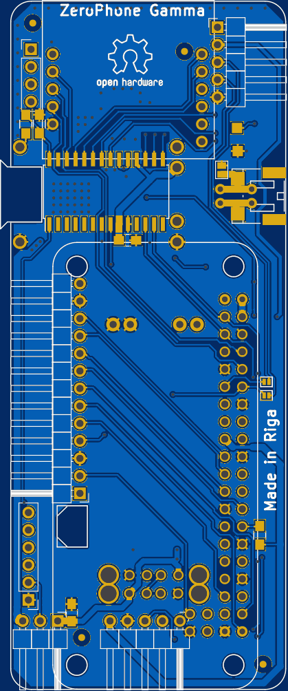
Now I have all the PCBs I need, except one - I have to make a 7x4 board which would house the 18650 battery holder I'm using. Other than that, I'm ready to order panels filled with misc boards. The soldermask is blue - to look like all the Chinese breakouts the phone is using =) After that, it's time for software work - all the things I didn't yet code, I'll be coding them now. For that, there's a separate worklog - go read it if you're interested in software problems that ZeroPhone is facing.
Now, on the changes. Pi Zero W release prompted me to rethink my GPIO function choices. See, here are the pins that I think need to be free:
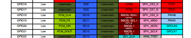
They have I2S, which is crucial if we want proper sound hardware on ZeroPhone. Otherwise, you could use the third SPI port of BCM2835 - SPI2 - even with 2 chip-selects, if we free GPIO17. So, I swapped the pins around and got a reasonable layout. Now I'm thinking I should free GPIO16 as well - this could be a good last minute change for gamma boards, now that I think about it =D
One of my ideas is to make expansion modules for the ZeroPhone using the connector that I2S is on - for example, to expose GSM audio to the system. However, the expansion headers on the sides won't be suitable for something that's supposed to be permanently attached. Instead, we could move the 5V DC-DC to in between the back board and Pi Zero (tricky, but doable) and then make boards which'd fit right where the USB DC-DC is right now - using castellated pads.
The beta back board was a mess. To fix it, I needed to simplify the schematic, rethink some of the design decisions and, sadly, get rid of some things I wanted to leave in. Even with the pin swapping, I've spent some time rearranging expansion header pins. For example, IR expansion header had +5V from the DC-DC, but when I looked at it once again, I understood it has to be routed diagonally through the whole board, from bottom to top right corner. However, the VBAT trace was right there near the IR header - and could provide more amps on demand, too (useful if you want to drive powerful IR LEDs, or maybe power a sound amplifier from that header) - so I've swapped +5V for VBAT.
I've also removed the level shifting circuitry that could allow one to use a 5V-only RTC like DS1307 - even though it would be nice to have, there was just no board space to properly route traces for it, and I2C traces looked like a mess with it.
ATMega header was one pin too wide for other headers to properly fit, so I had to make it a 6-pin header - however, it's now a "FTDI-compatible" header, meaning that it has the "GND-GND-VCC-TXD-RXD-RST" pinout. It can even work with 5V "FTDI" programmers, as long as the front board is disconnected from the Pi Zero (which is to be attached to the back board anyway). I left out the spare ATMega GPIO - but there's a solder jumper you can use to bring it back, so it's is not that bad =)
Here's a Google document with the pin mappings for alpha, beta and gamma boards. This is more of a wiki material, so the ZeroPhone wiki will appear sooner or later, once there are enough materials to put there.
In other news, I made a beta board release. For me, making a hardware release means listing both the features and the bugs - changes from the previous version and changes that'll have to be included in the next version. This will change once there's some kind of wiki in place - so that there's another place to keep track of bugs and features as they appear, and not only when the boards have been tested.
Discussions
Become a Hackaday.io Member
Create an account to leave a comment. Already have an account? Log In.