Close
0%
0%

G-EDM

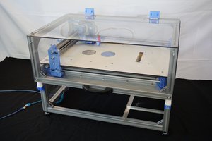
The G-EDM is an electrical discharge machine that supports sinker EDM, EDM engraving, EDM drilling and Wire EDM operations. #Drahterodieren

Similar projects worth following
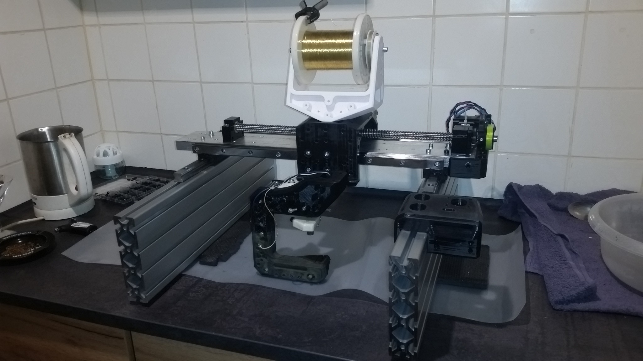
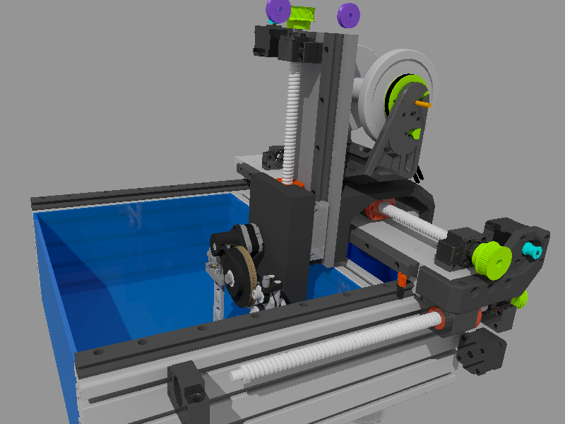
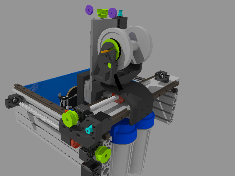
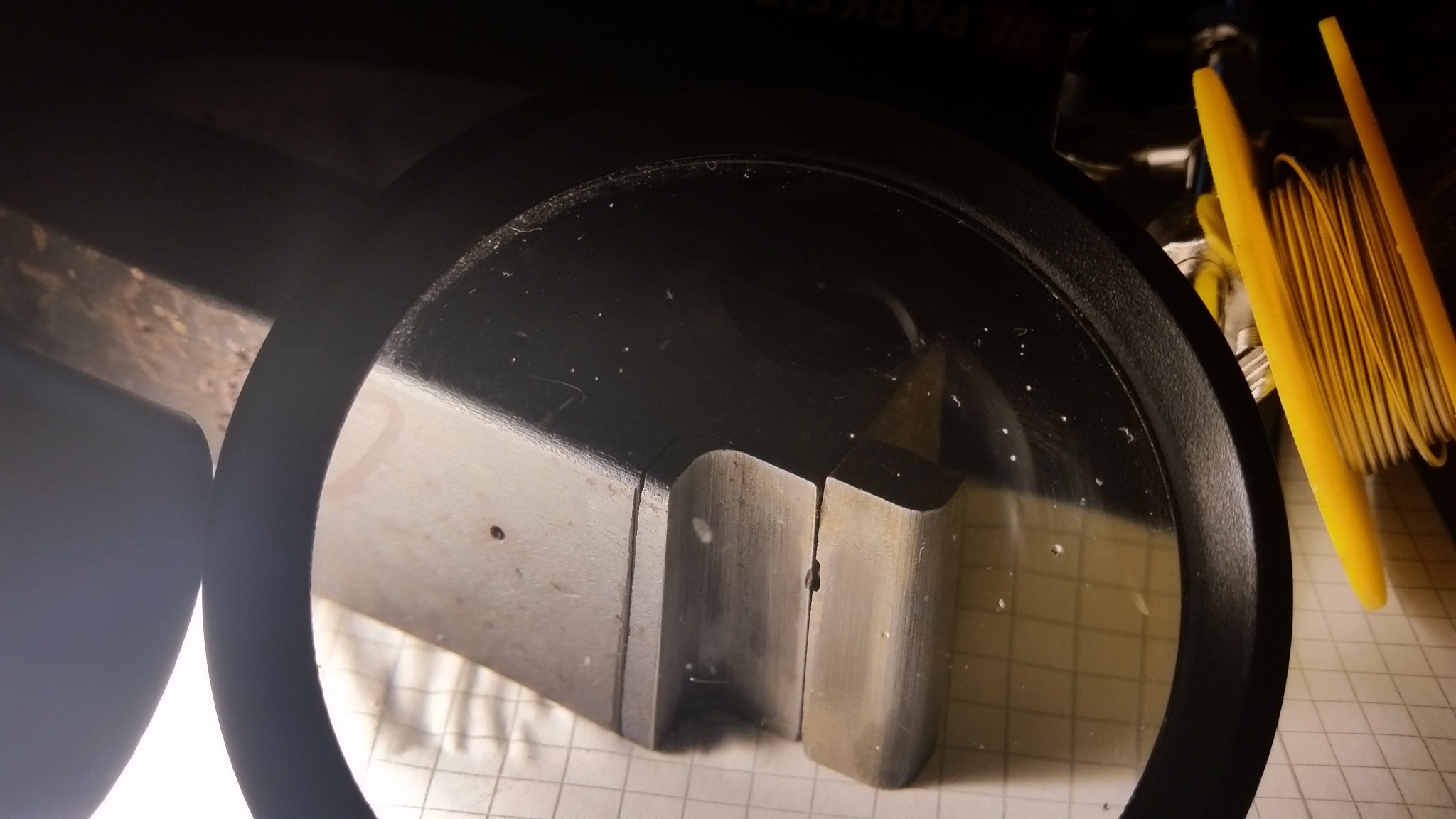
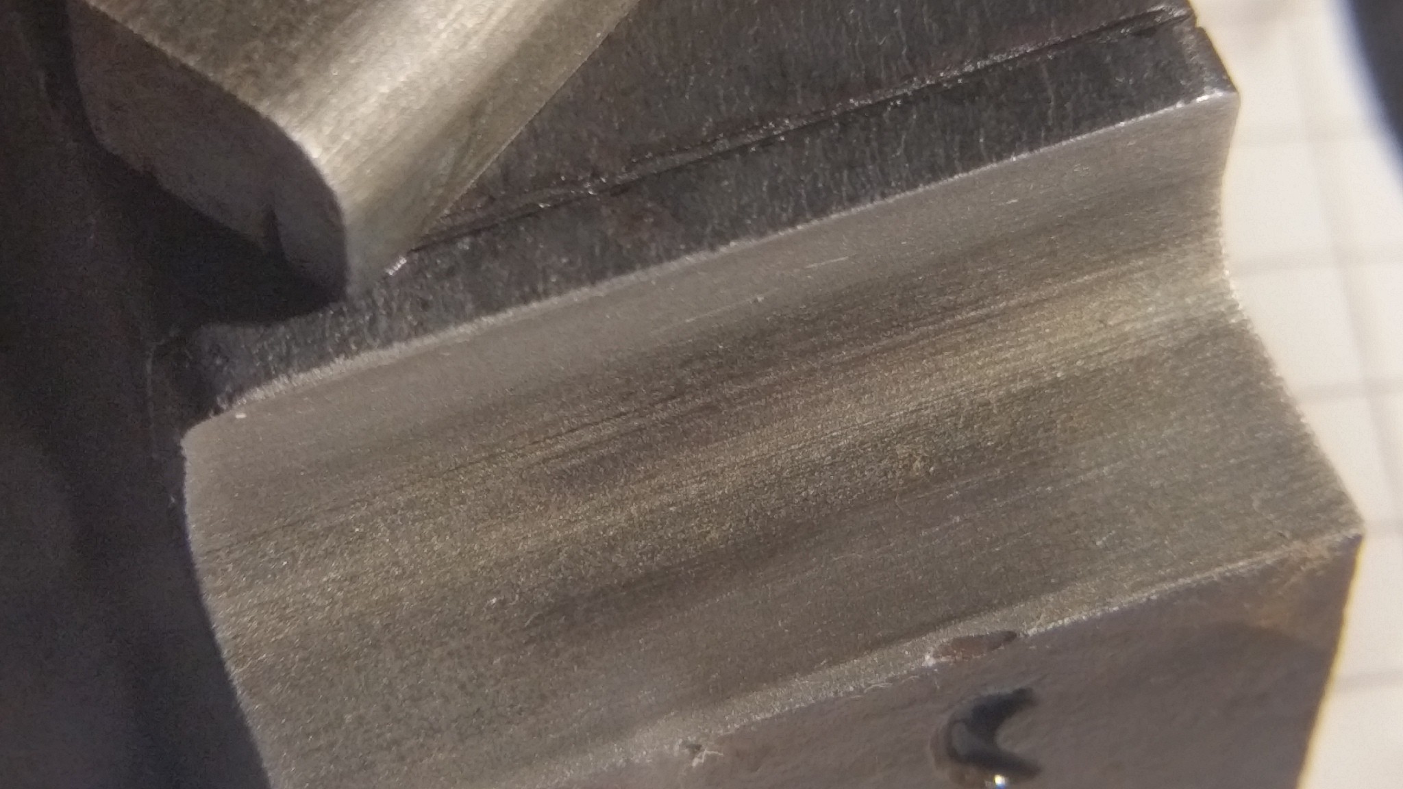
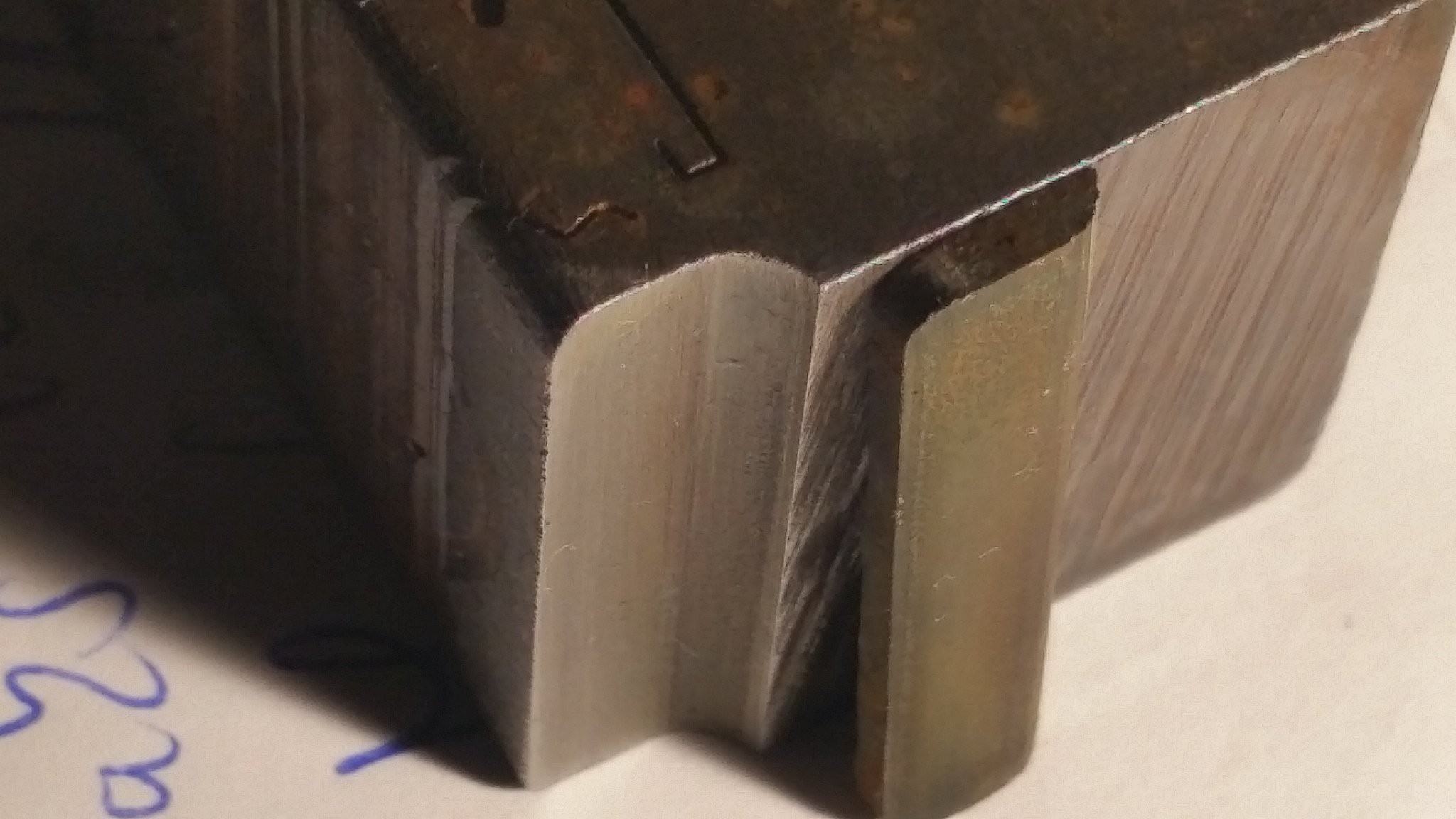
The G-EDM is a fully automated based three axis EDM CNC machine that supports different kinds of electrodes like brass tubes or brass sheets and is highly customizable. With the new wire EDM extension it is possible to cut high precision parts out of aluminum, mild steel, HSS and other metals. Besides normal operations like drilling and wire EDM it also provides an experimental EDM engraving mode that uses a normal brass rod as a floating electrode to engrave text into metal or erode pockets.

It uses 3D printed parts where it is possible and in the future it may support even laser and mill operations.

The G-EDM pulsegenerator is basically a modern buck converter based pulse power supply that does not need a power resistor.

All PCBs use big ground planes, feedback signal traces are fenced with via stitches and in general all ground zones on different layers are connected together with via stitches to get the best possible performance out of it.

The G-EDM ( new video )

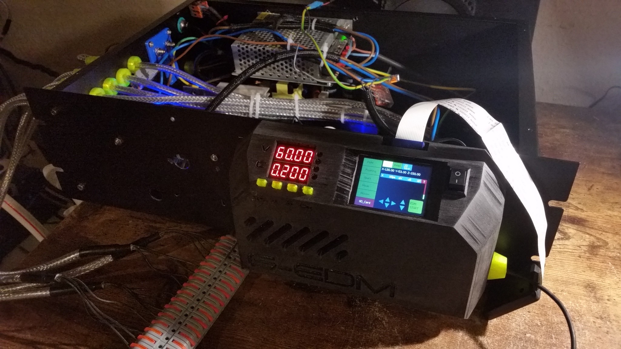
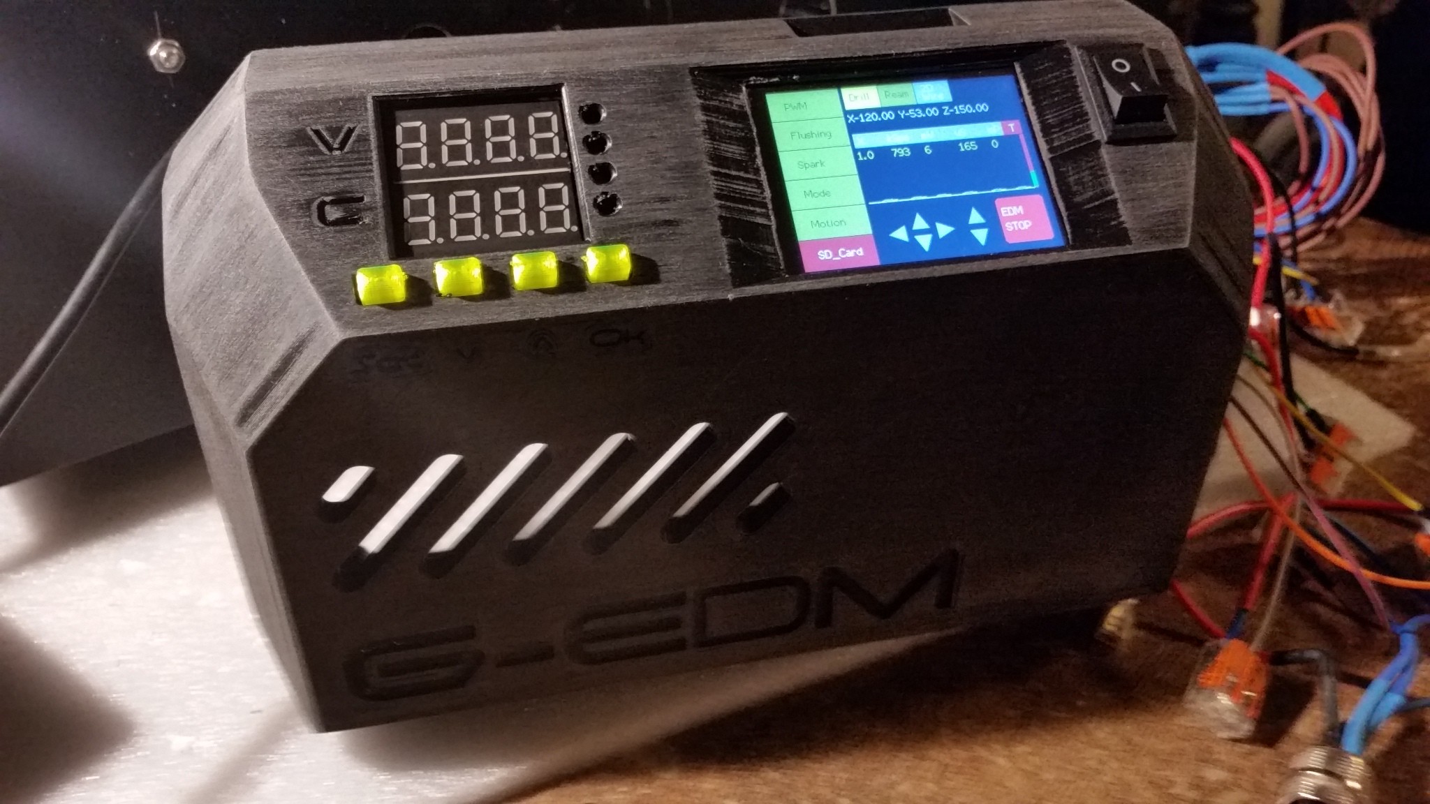
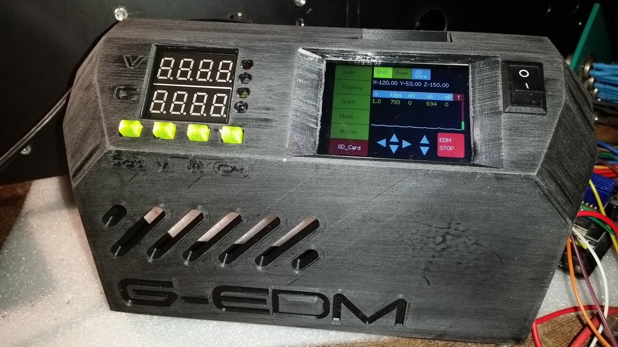
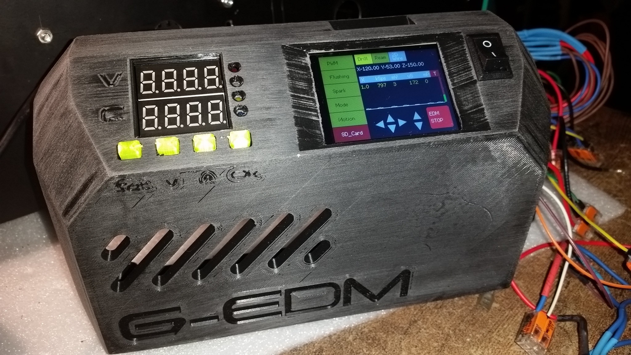
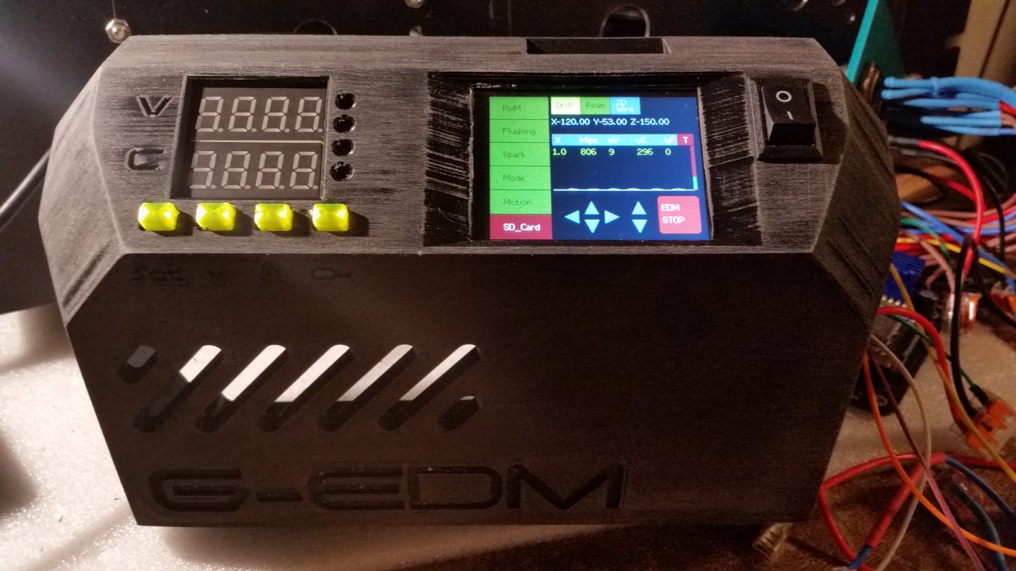
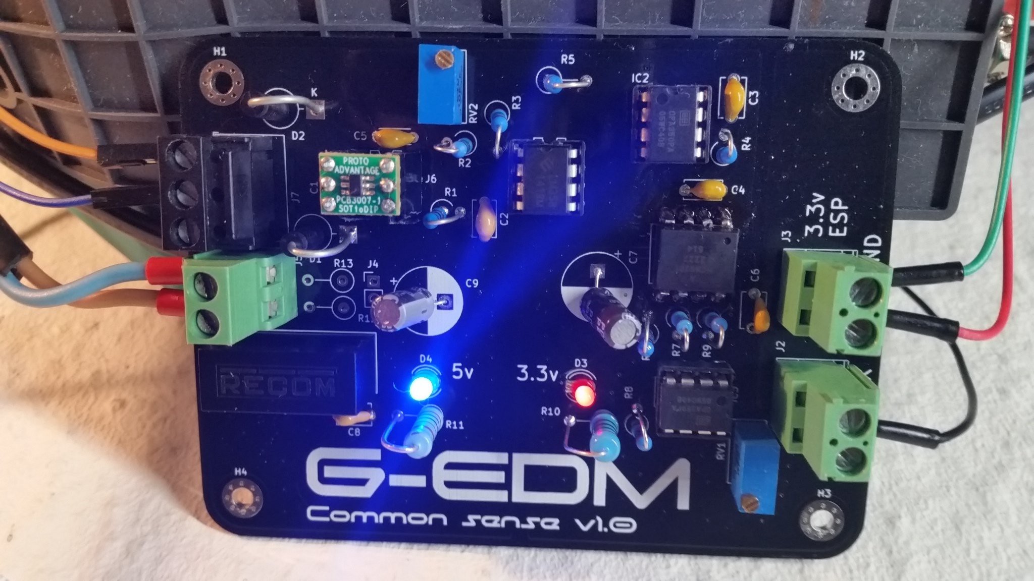
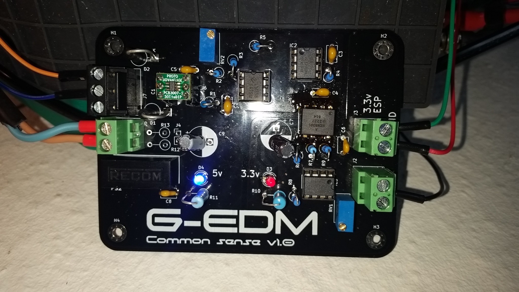
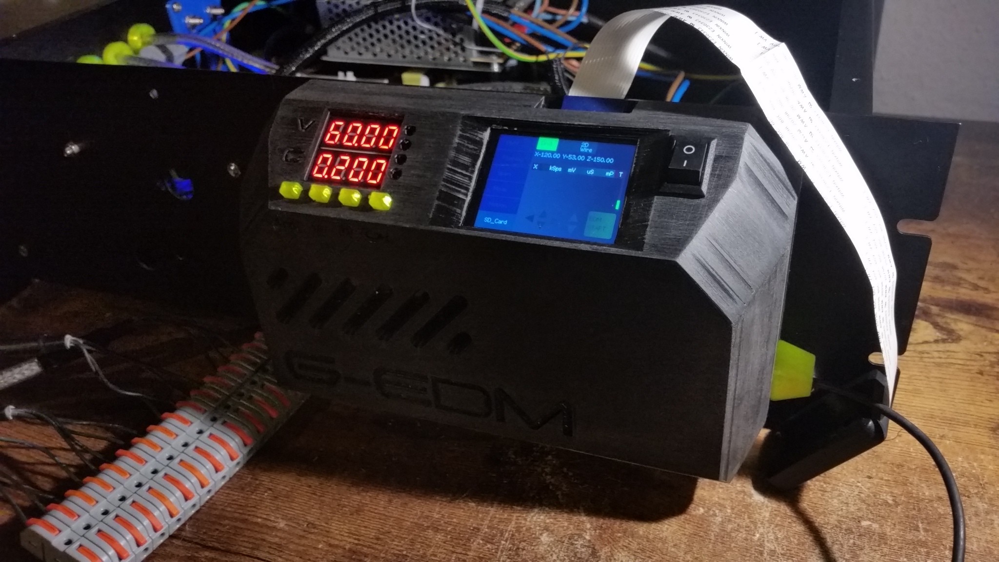
The final version of the control panel:


And more details:
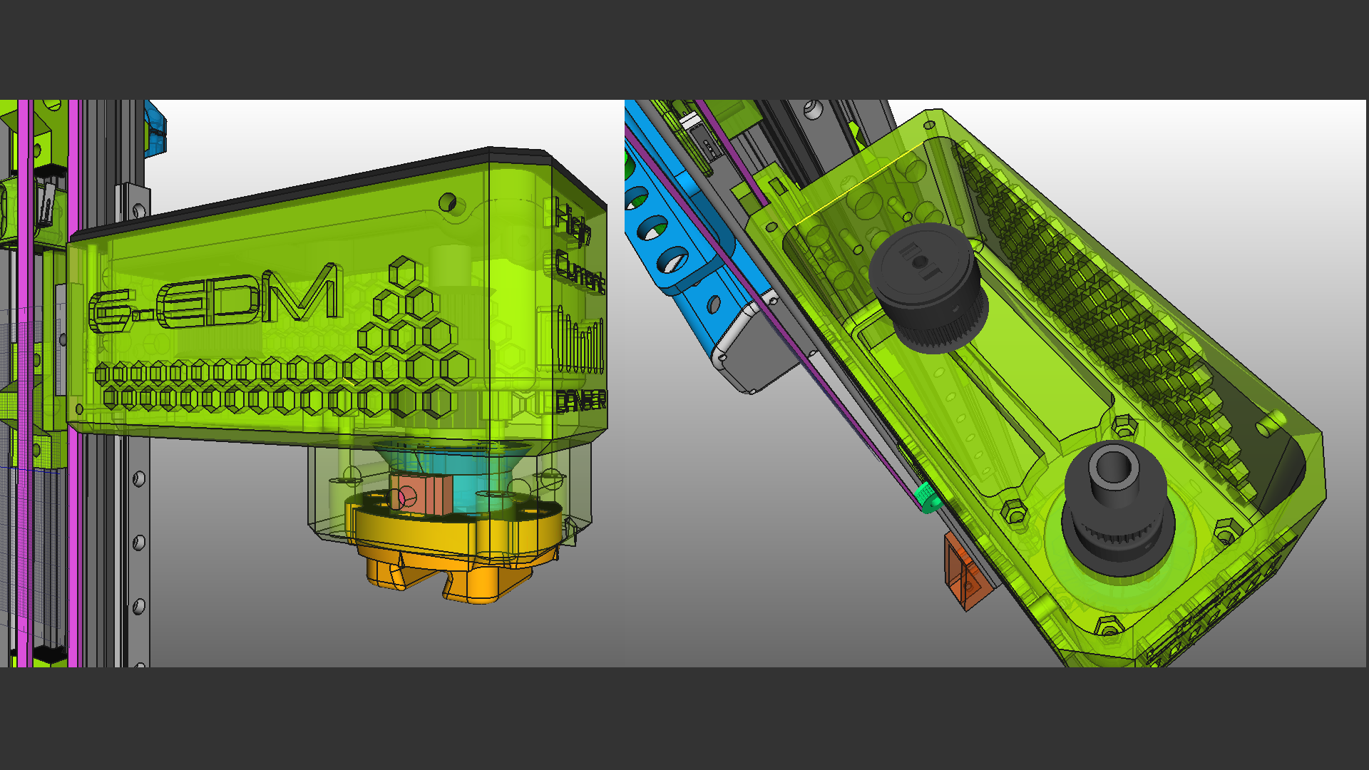

EDM can create a lot of EMI noise and therefore the spark generator needs to be in a shielded enclosure. But even the electrode and the spark itself create noise.

In the first builds the negative spark wire was mounted to the rotary drill chuck within the tool head. But this converted the electrode into a antenna with enough power to shut down the communication between the ESP and the display.

This highly depends on the Amps used, the duty cycle of the pulse and the length of the electrode but I decided to just connect the electrodes as close to the work piece as possible.

For round electrodes the blank wire is wrapped around them and for sheets alligator clips are good.

It doesn't look as good as the integrated contact but it reduces the noise a lot.

The pulse generator is a pretty basic and flexible concept that is easy to replicate. A 65v switching PSU is connected to a DPM8605 step down module that will provide 0-60v and 0-5A. The DPM converts the pulseboard into an inductor based pulse generator.

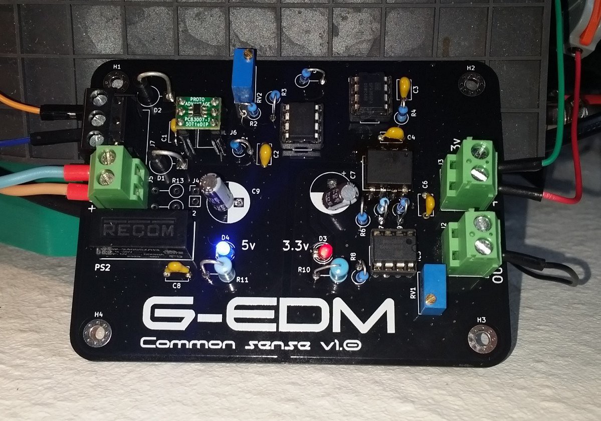
The output of the DPM8605 is then connected to the pulse generator PCB which is basically just a Mosfet gate driver, some capacitors and a voltage divider for the feedback signal.

This is the pulse generator PCB ( prototype ) wired up for some basic tests.

At the moment there are two working versions of the pulseboard that drives the sparks of the G-EDM.

A tiny board that uses an opto-isolated gate driver to switch external mosfets:

And a big board with up to 6 integrated Mosfets and a discrete gate driver circuit and two shiny indicator LEDs.

View all 60 project logs

Enjoy this project?

Share

Discussions

Mike K wrote 03/13/2024 at 13:31 point

Amazing work. I am waiting for the PCB files to build and test one myself. I had made an edm machine in the past but my spark wasnt strong enough. Hopefully this board works in my machine.

  Are you sure? yes | no

dgourlay wrote 11/22/2023 at 22:44 point

this is GREAT!  I just saw your youtube.  Excellent work!

  Are you sure? yes | no

gedm-dev wrote 11/23/2023 at 07:41 point
Thanks. Wish it would be finished soon. But still so much to do.

  Are you sure? yes | no

H wrote 10/06/2023 at 00:59 point

Looks amazing so far! As far as I know there haven't been any other EDM makers that were willing to share their files, so thanks (even though you're not to that point yet)!

  Are you sure? yes | no

gedm-dev wrote 10/06/2023 at 02:19 point

The only thing unreleased are the PCBs and people may be surprised how simple they actually are. The ESP motion controller is jsut a breakout board that makes life easier. The pulseboard is a little more complex but still pretty basic. At some point they will be available.

  Are you sure? yes | no

H wrote 10/06/2023 at 23:51 point

Oh dam I should look more into this. I don't need the motion board since I already have individual drivers + breakout boards that are easy to wire

  Are you sure? yes | no

gedm-dev wrote 10/07/2023 at 00:34 point

The breakoutboard is very useful. It extends the SPI Mosi/MISO/CLK pins and allows to wire the display without hacking 3to1 jumper wires.

  Are you sure? yes | no

Jimmy wrote 10/04/2023 at 08:44 point

Does your GRBL version backtrack on short?

  Are you sure? yes | no

gedm-dev wrote 10/05/2023 at 07:26 point

Yes. The planner of grbl was replaced with one that can move back in history.

  Are you sure? yes | no

Piotr wrote 08/10/2023 at 00:00 point

How feedback circuit looks like? I want to build similar machine and have problem in this part.

  Are you sure? yes | no

gedm-dev wrote 08/10/2023 at 01:31 point
The feedback is just a voltage divider. that outputs between 0 and 2.8v depending on the voltage drop created. Everything else happens at software level.

  Are you sure? yes | no

joram wrote 07/12/2023 at 08:48 point

This looks interesting. Is the esp32 code already in a sharable state?

  Are you sure? yes | no

gedm-dev wrote 07/12/2023 at 12:49 point

Almost. I just need to confirm that the Y axis works too. Currently building the axis. Should be ready soon.

  Are you sure? yes | no

Similar Projects

Does this project spark your interest?

Become a member to follow this project and never miss any updates