0%
0%
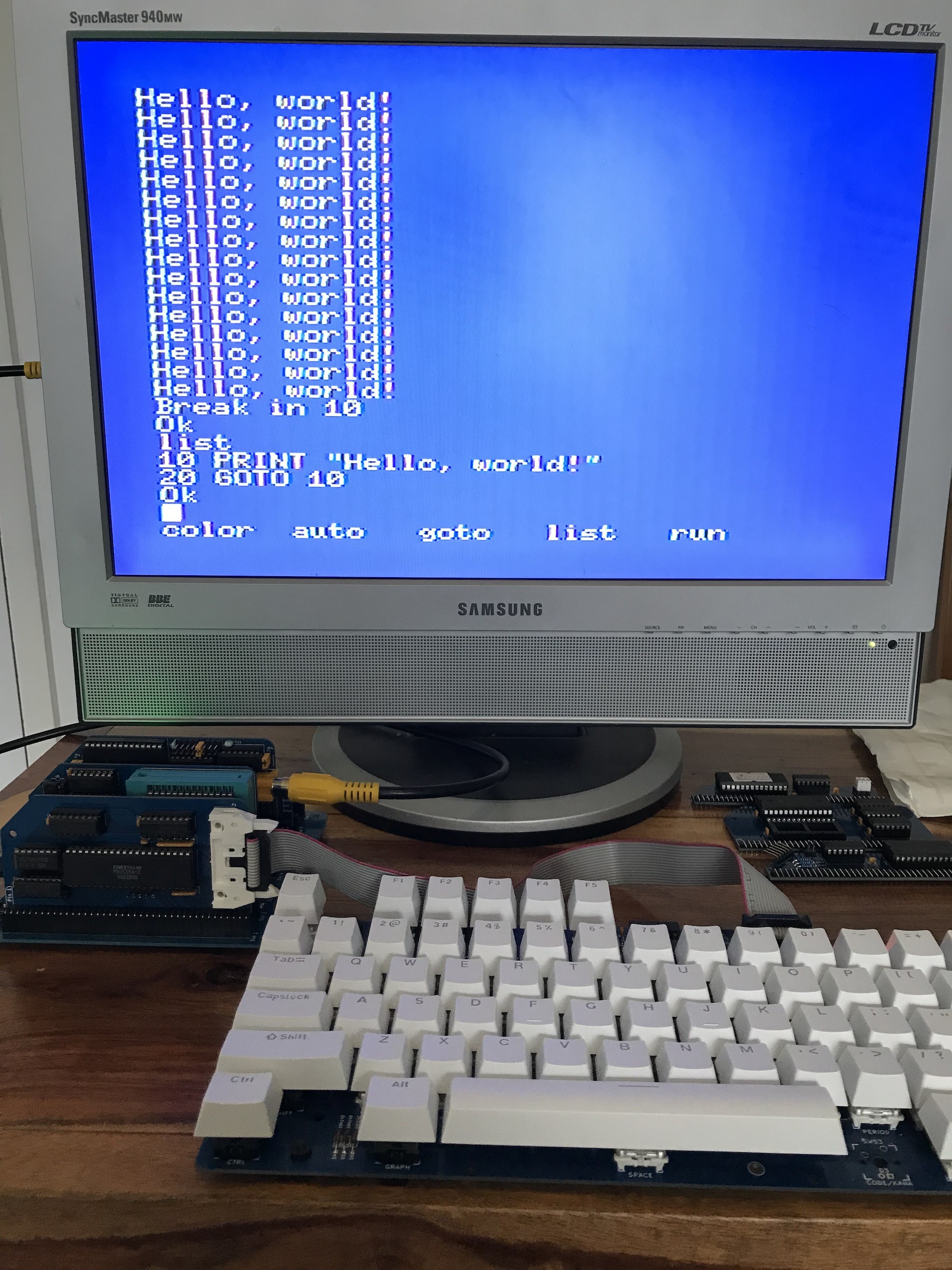
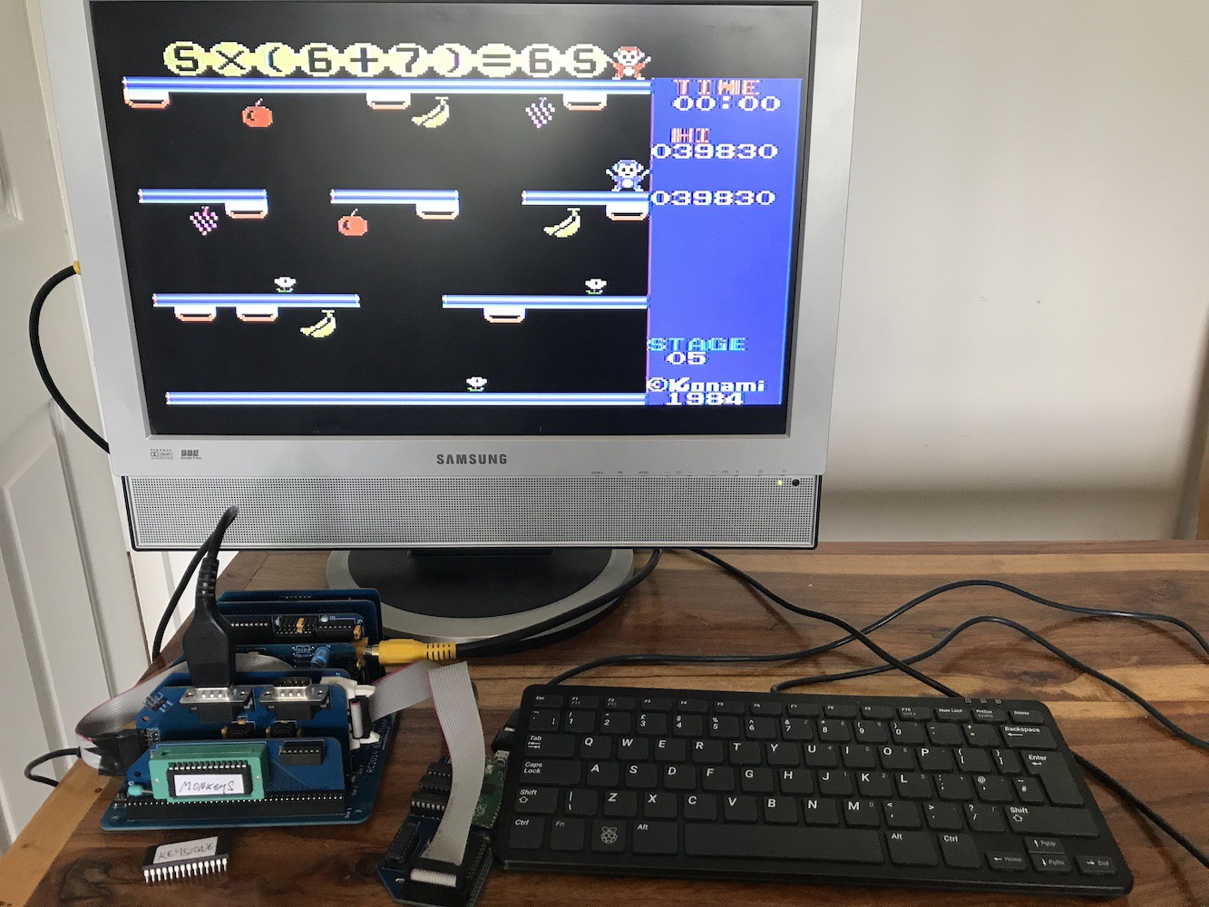
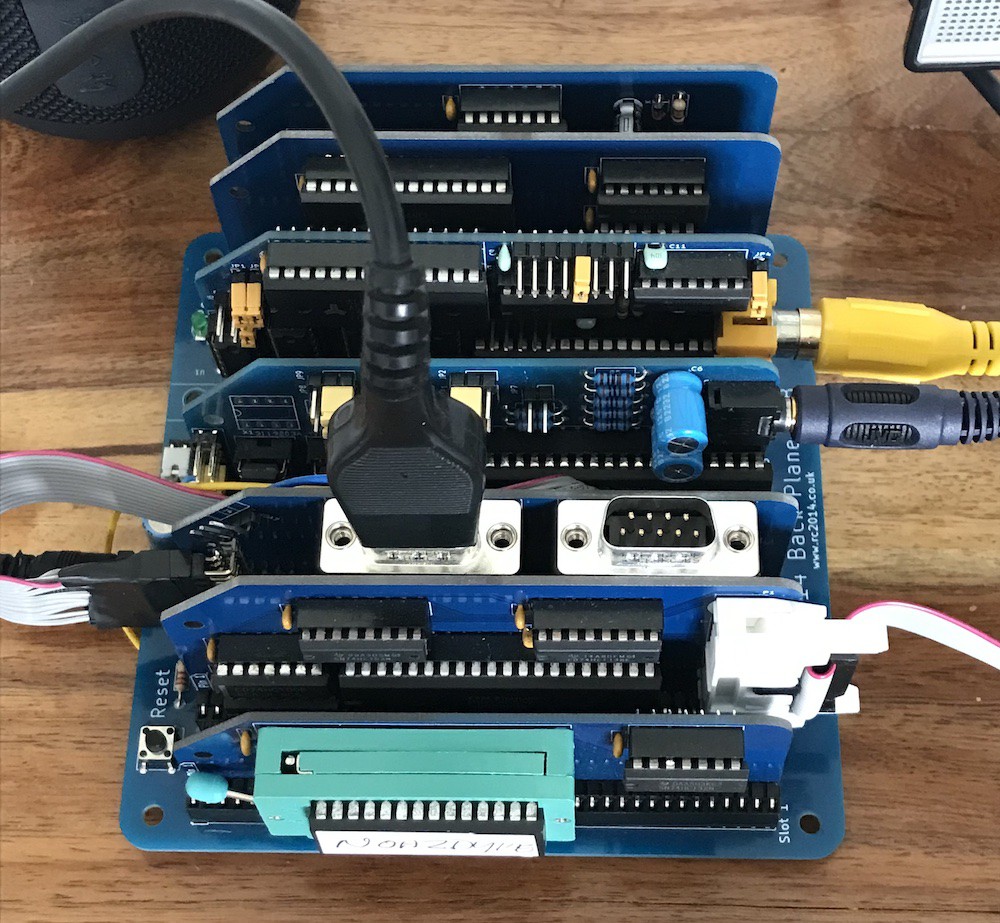
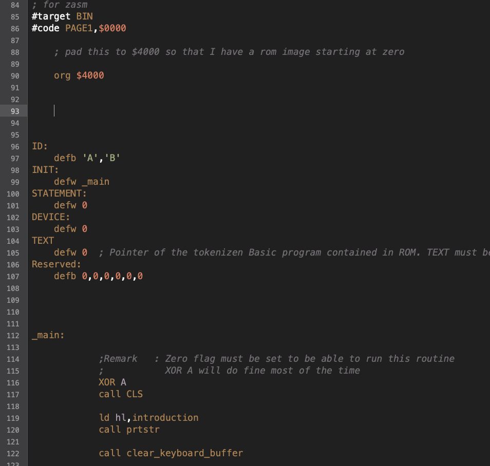
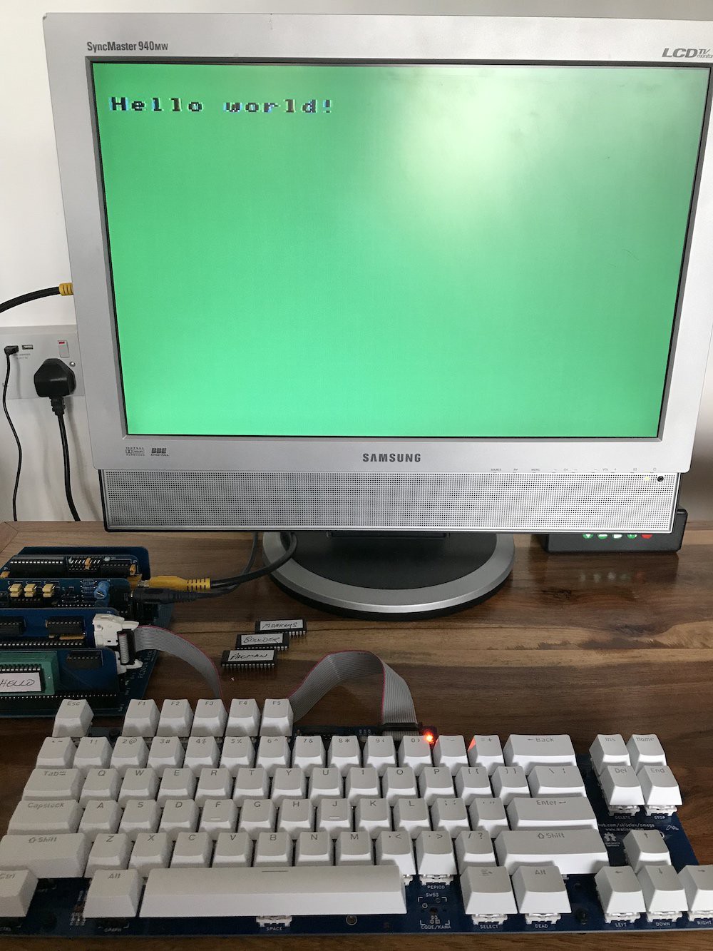
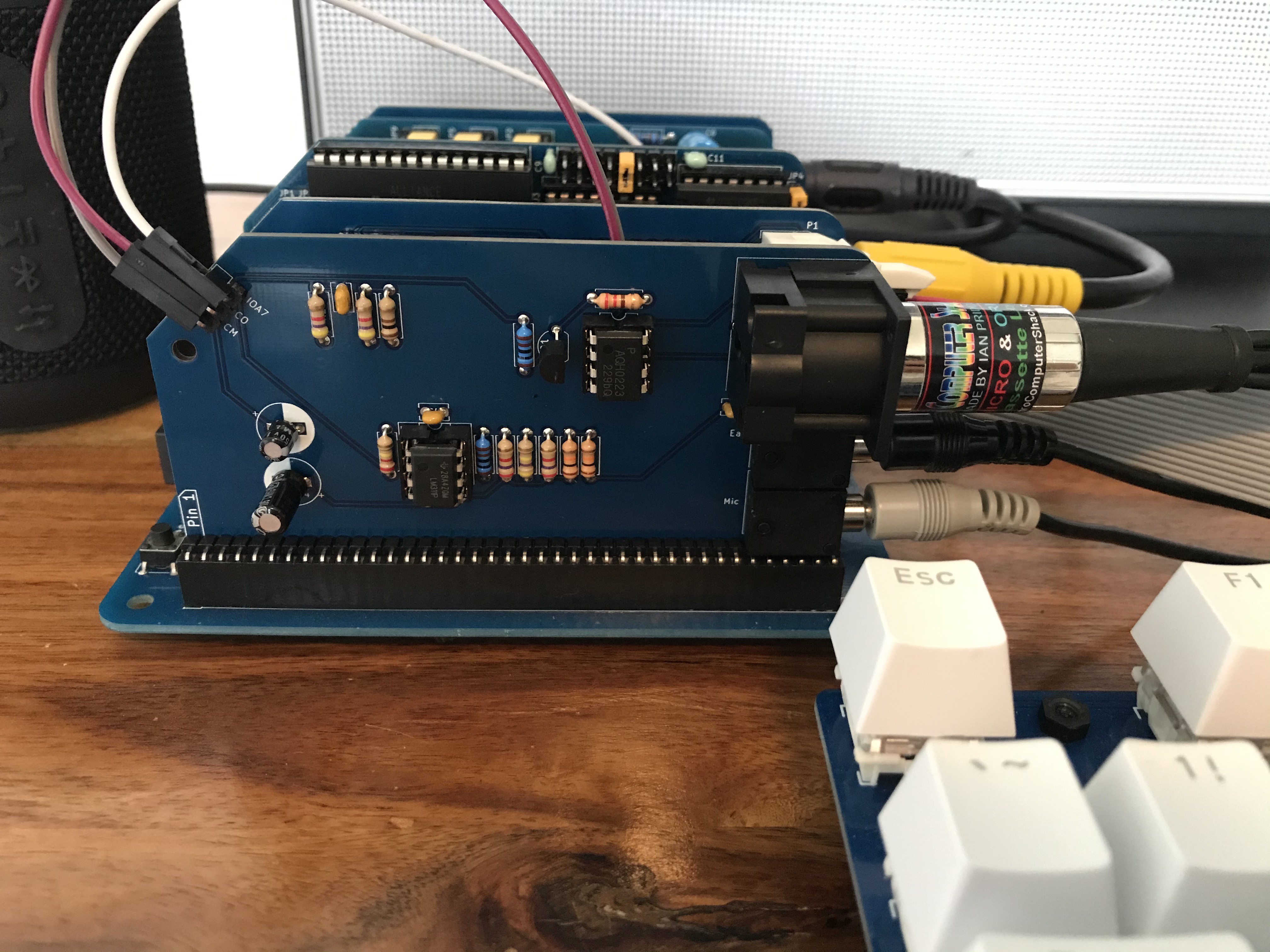
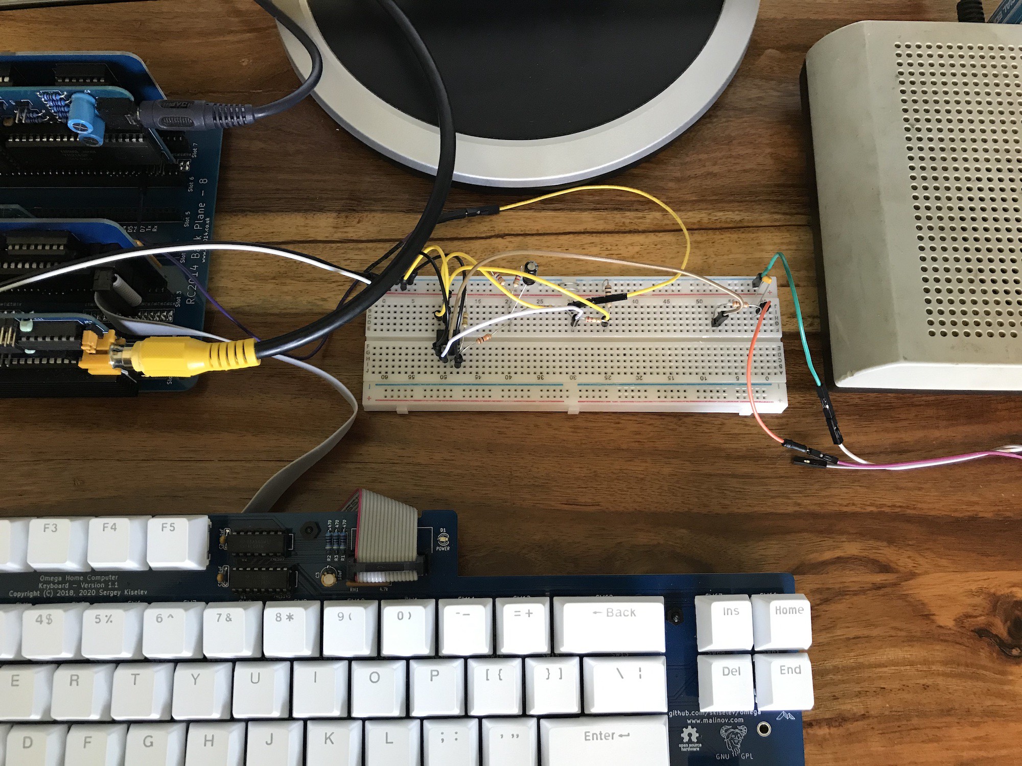
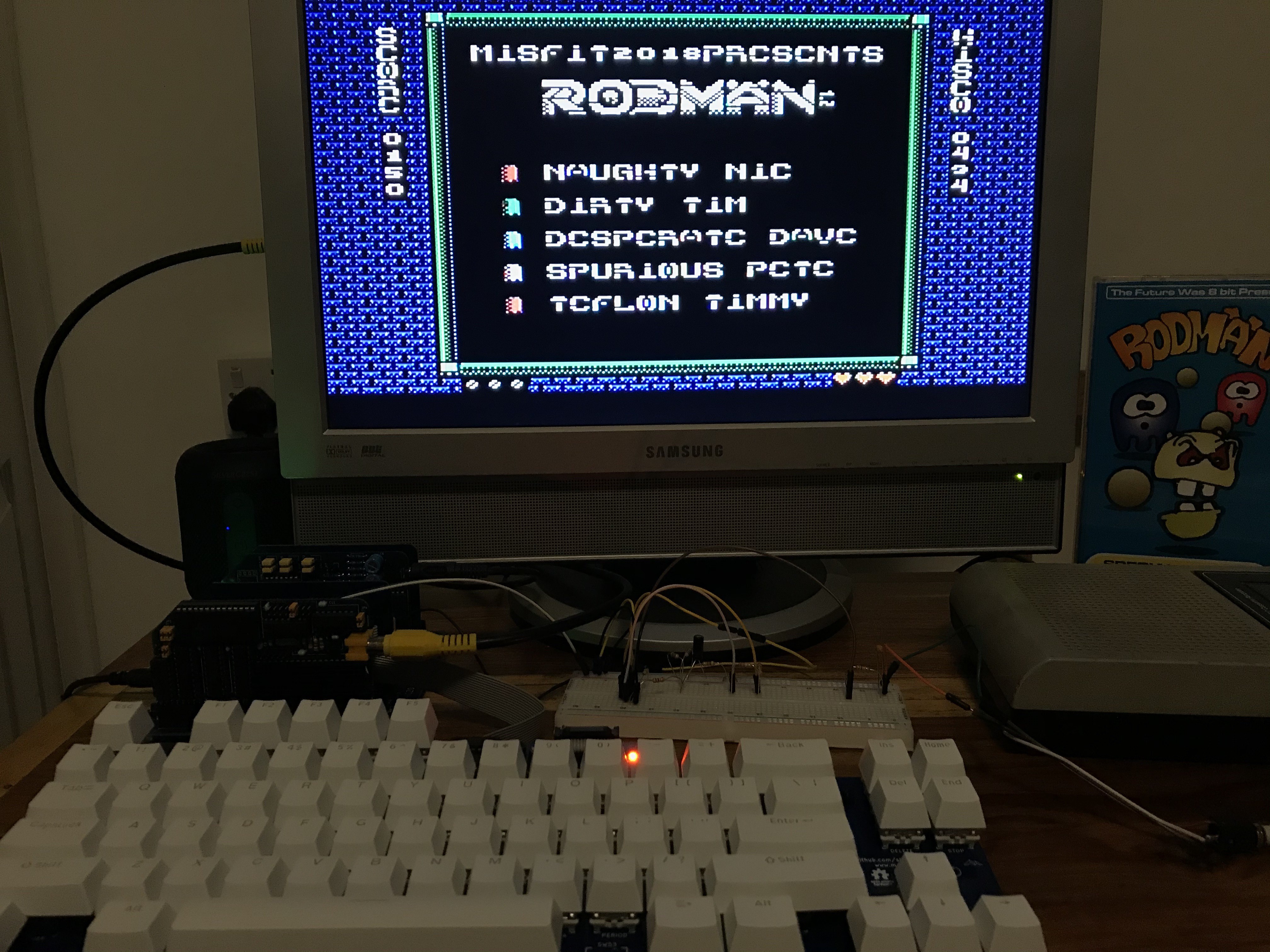
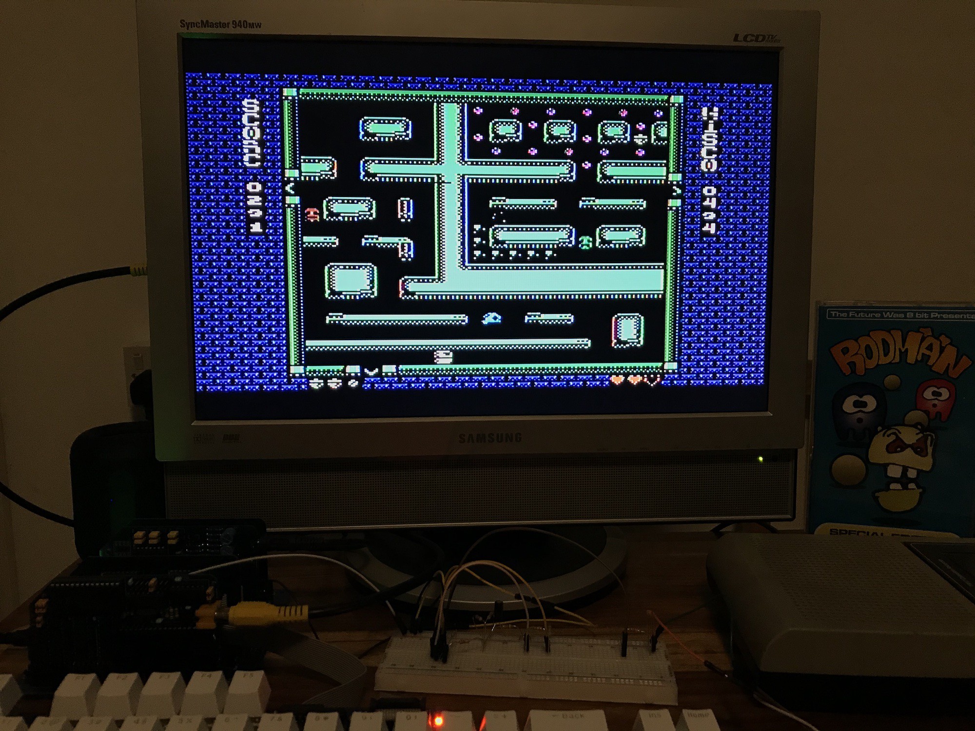
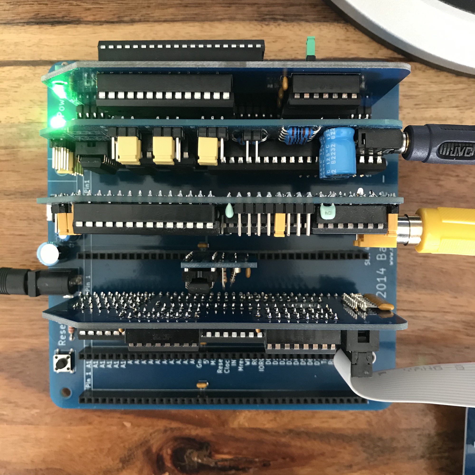
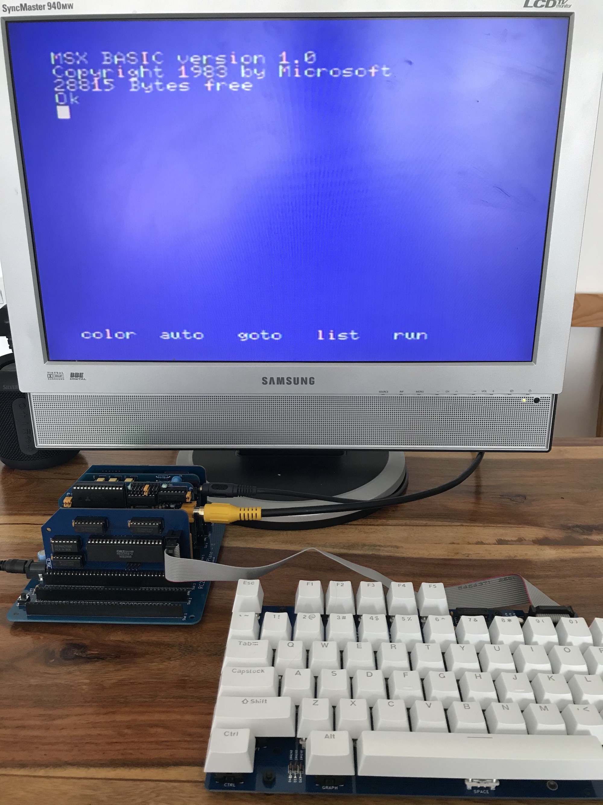
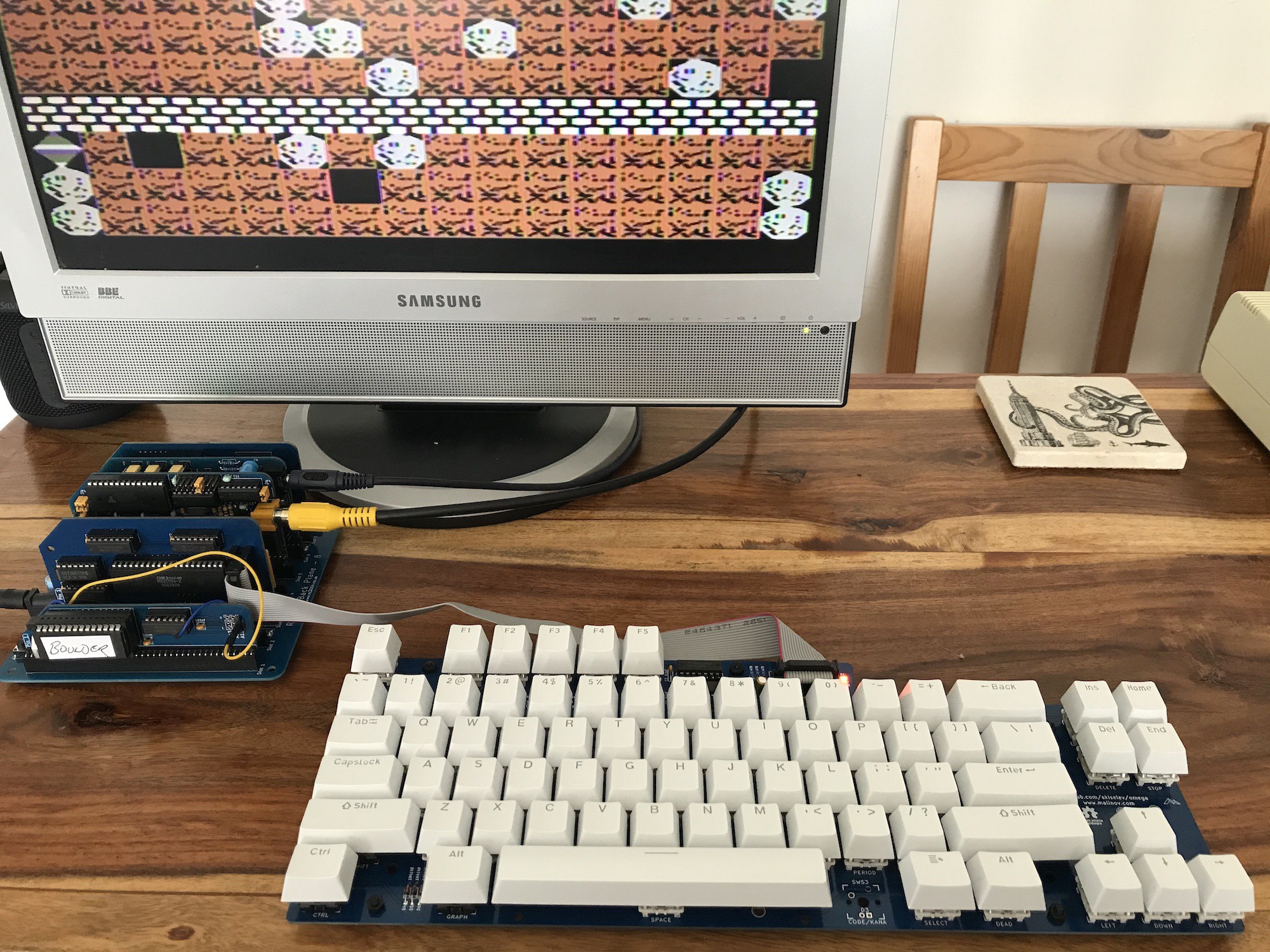
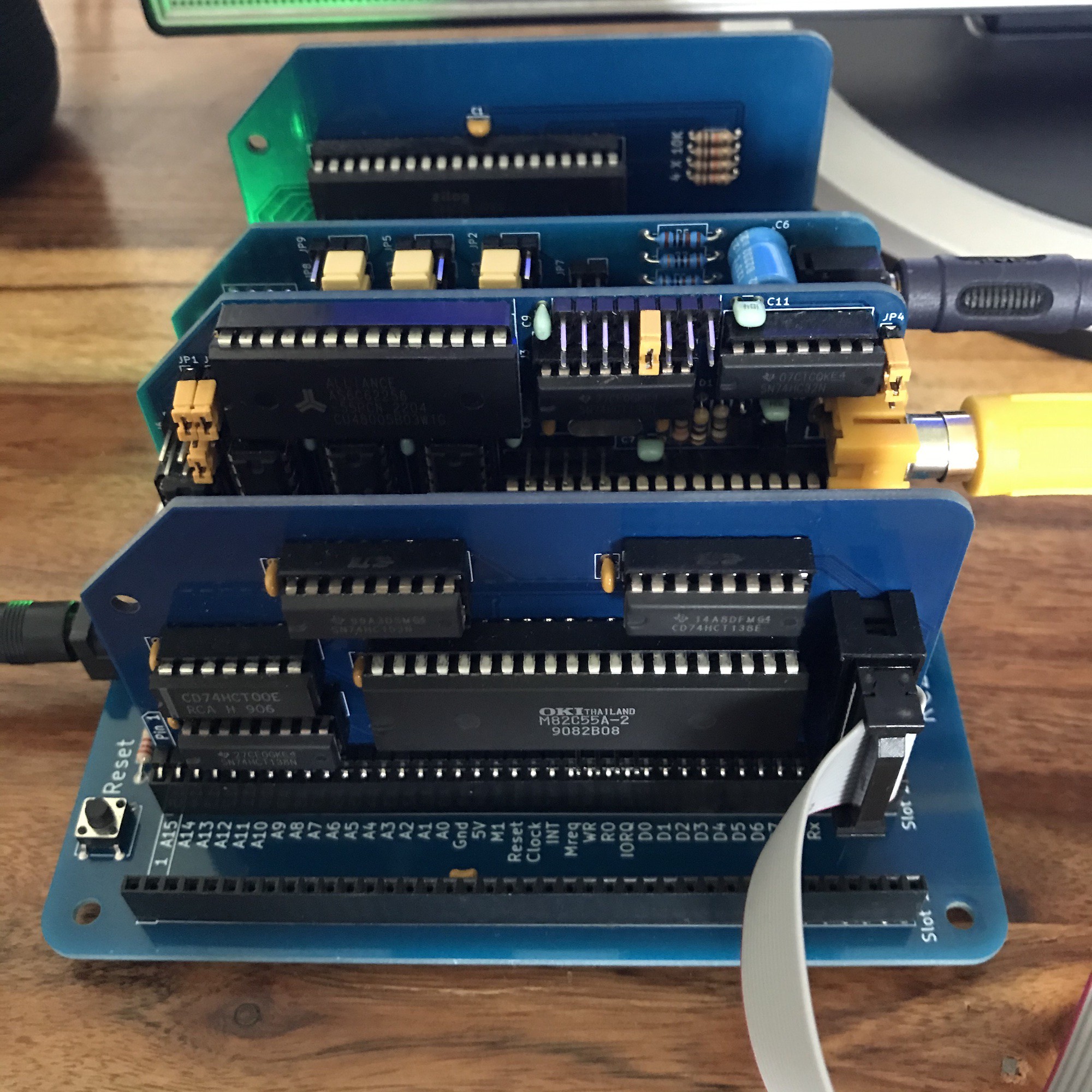
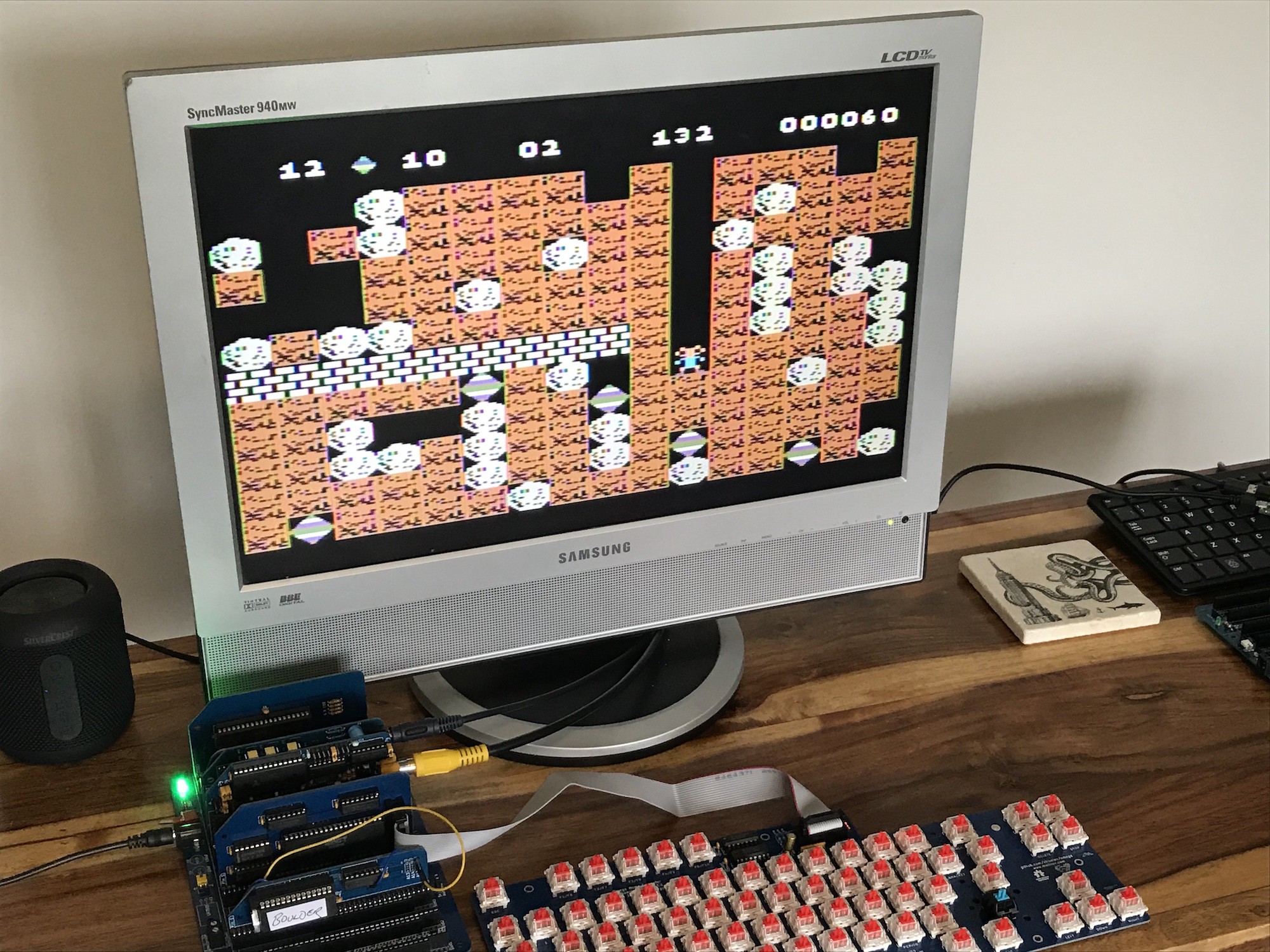
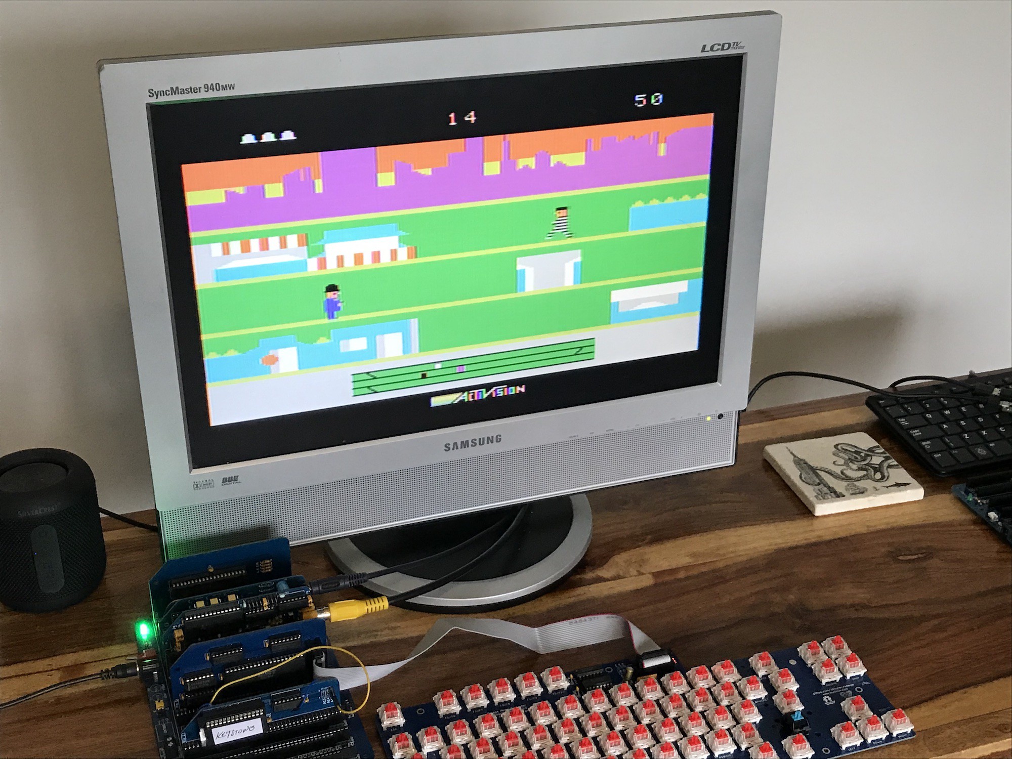
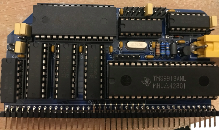
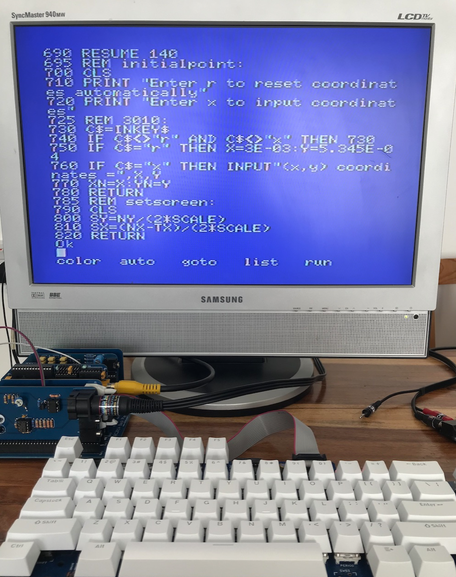
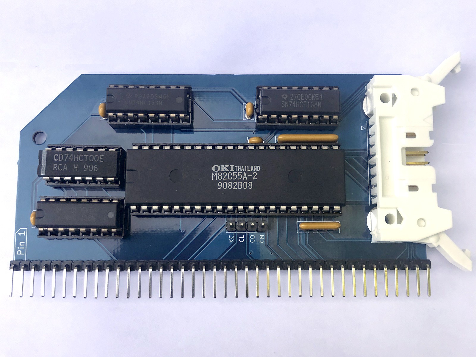
MSX on RC2014
in which I attempt to make an MSX1 compatible computer using RC2014, keeping to standard RC2014 backplane and modules as far as possible.
Become a Hackaday.io member
Already have an account? Log in.
Just one more thing
To make the experience fit your profile, pick a username and tell us what interests you.
Pick an awesome username
hackaday.io/
Your profile's URL: hackaday.io/username. Max 25 alphanumeric characters.
Pick a few interests
Projects that share your interests
People that share your interests


 Justin Skists
 Matt Bradshaw
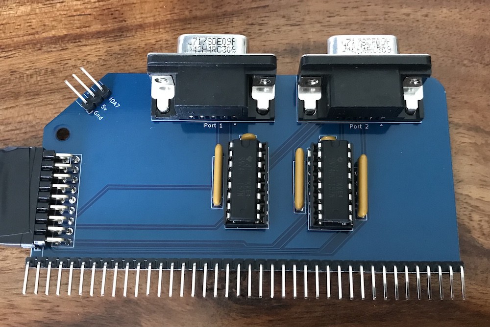
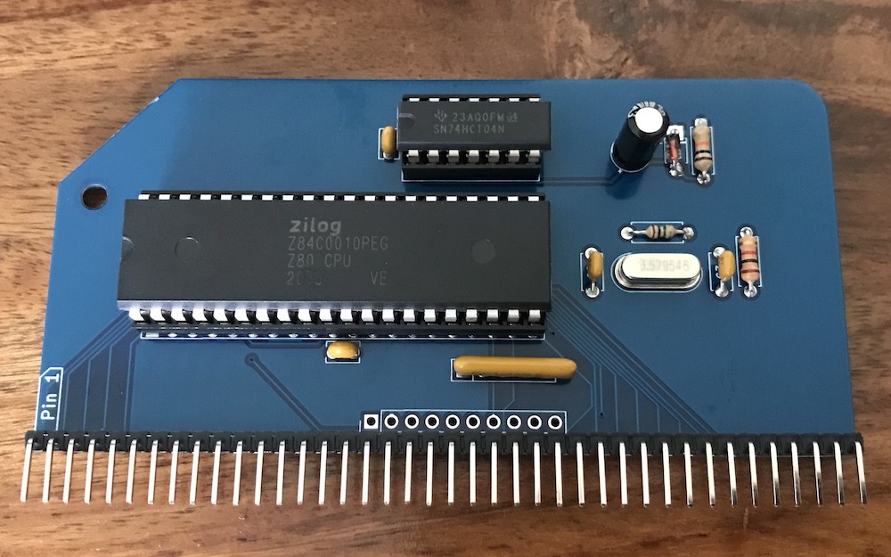
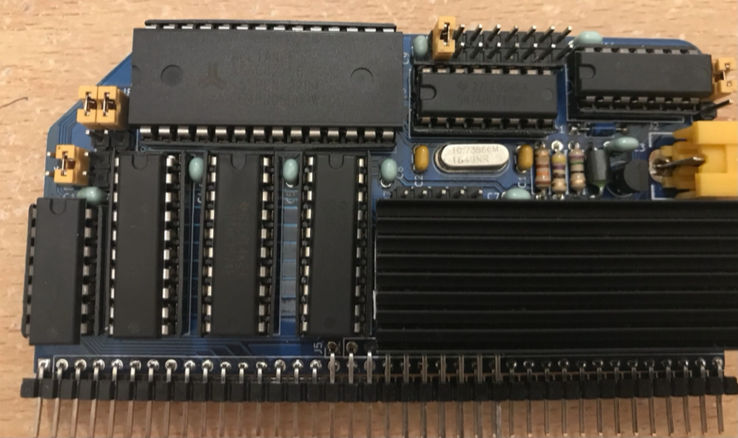
That's good to know, thank you. Is there any reason why those specifying the MSX1 standard chose the NTSC frequency? The TMS video chip that they specified (VDP) requires its own signal of ~10.68Mhz and has its own crystal in MSX computers (and J B Langston's video module which we're using here). I don't think the original MSX machines (from various manufacturers) always stuck exactly to the 3.58Mhz.