0%
0%
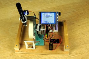
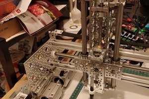
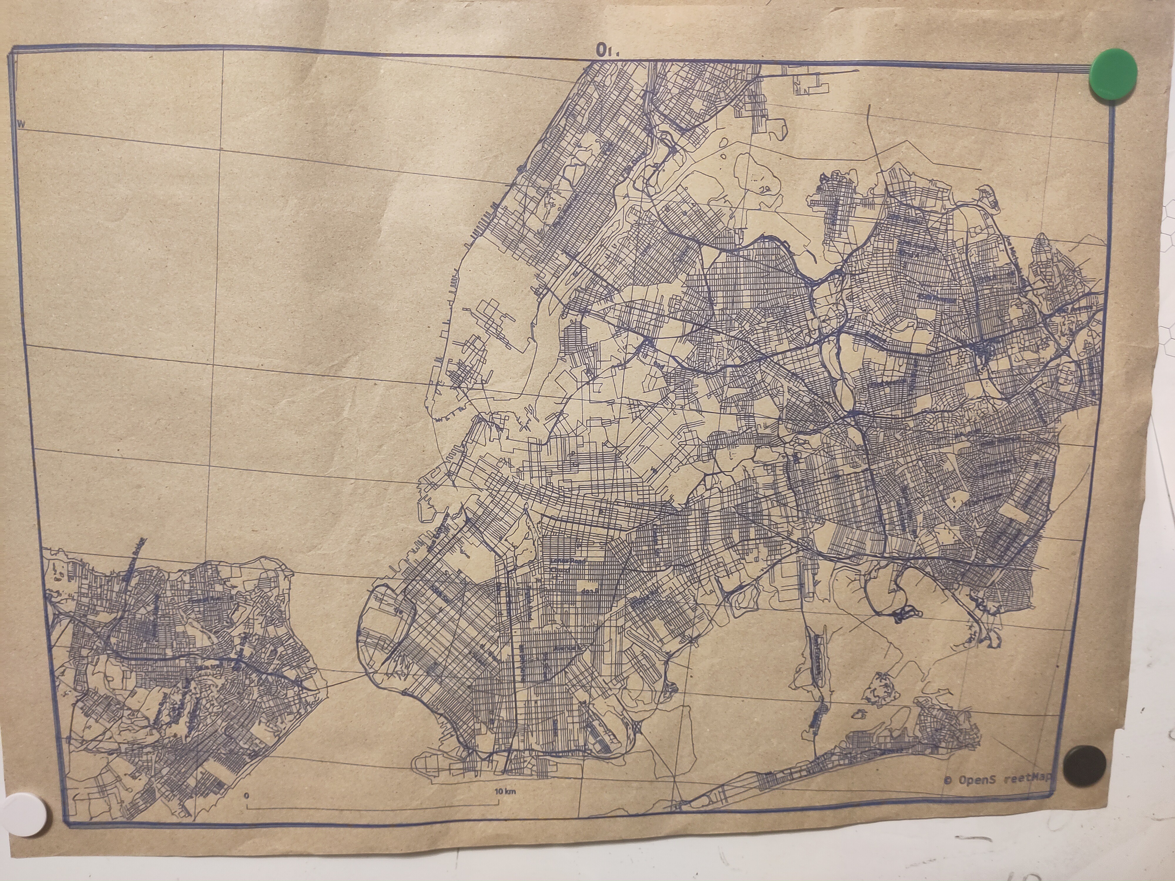
Big roller based plotter/vinyl cutter
~700mm plotter with roller based Y movement
 Kārlis
Become a Hackaday.io member
Already have an account? Log in.
Just one more thing
To make the experience fit your profile, pick a username and tell us what interests you.
Pick an awesome username
hackaday.io/
Your profile's URL: hackaday.io/username. Max 25 alphanumeric characters.
Pick a few interests
Projects that share your interests
People that share your interests

 Ted
Ted
 Paul McClay
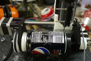
Thank you for the updates , I really like your project. you really did make progress on most of the work it takes to scale your project further and answer the basic question and research to get it to work.
One reason this is interesting to me is a do a lot of mylar cutting, specifically 7mil. Cricut software has been an issue and silhoutte cutter really lack force and both cost around $400. I wanted a offline, reliable and repairable plotter solution. I was thinking of trying to make something similar since i have a couple 3d printer boards lying around and your post answer all the question I had in mind.