 Paul McClay
[*]Well, I guess the "nearly free" party's over because the subsidy's over but a dollar store franchise sold stacks of this "advanced 7 outlet power strip with adjustable threshold" for a while:
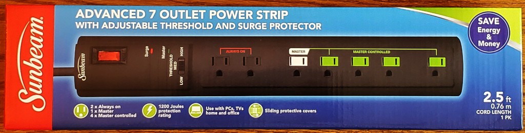
Maybe you bought some. Because dollar. Now that I'm finally getting around to writing this up, approaching a year after the fact, they're more like $8-10 which is still pretty cheap for what it is and a lot less than retail cost of parts to make anything like it. Several sellers on a popular auction site offer lots of 14 for <$5 each. (...nor either buy thou thirteen, excepting that thou then proceed to fourteen. Fifteen is right out.)
Dear reader: this is random Internet "content" by an unqualified author for entertainment only. Misuse of the thing in the box in the picture can kill you and burn your house, which may entail killing other people. How to do anything with this device other than what the label says without burning stuff or killing people is beyond the scope of this writeup. Consider this first-person account as a pre-staged footnote for my eventual Darwin Award and not as instructions for anything you should do.
Anyhow...
I was considering options for a logic-switched AC power outlet when I went to the dollar store one day and saw a wall of these things, which looked like they must include most of the parts I didn't want to buy. And must have passed at least some degree of responsible adult scrutiny. Where "responsible adult" includes no one at UL.
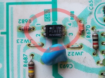
Inside there are two PCBs -- the relay module and a 5V (iirc) DC supply -- and some bad soldering.
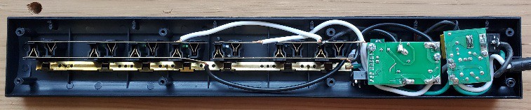
Alas I didn't take any pictures of the component sides of the PCBs. Not much to see: the relay module has a relay, a transistor for the coil, an IC that apparently does the load sensing, and some jelly beans; the power supply has power supply stuff. I didn't take any pictures of solder joints either. Some capture only some strands of the power conductors, which were apparently held during assembly without any mechanical attachment so re-heating them looked like a pain. So, um, I'll derate a bit -- which my intended use allows -- and maybe UL will co-sign my Darwin Award.
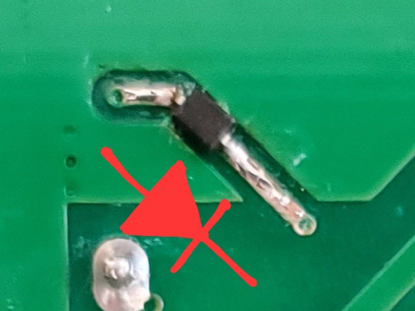
On investigation, I found one of the traces on the exposed bottom side of the PCB carries the signal that controls the transistor that controls the relay coil. Here I've already scraped off the solder mask:
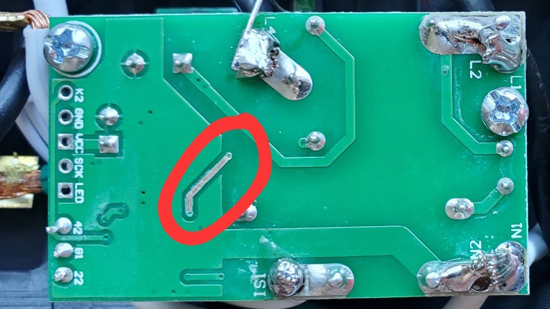
This is convenient, or will be if I ever hack another one of these, because getting at the other side of the board requires some de-/re-soldering.
Voltage on that trace went from GND to VCC when the load sensing circuit closed the relay. I don't remember if I determined whether the transistor was a FET, or bipolar with a base resistor downstream from this point, or didn't bother because the signal was volts at this point regardless.
| ➽ ➽ ➽ | While we're here: GND, VCC, and LED look mundane but SCK suggests something interesting, maybe, but appears to have no friends except K2 and what's that?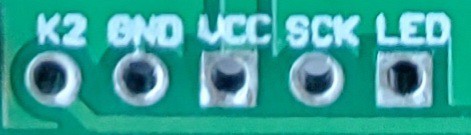 |
It would have been nice if the controller set its signal output to high impedance when inactive but it pulls the line low. So no "wired OR".
After cutting the trace and verifying that connecting the far side to VCC activated the relay, I went shopping in my ̶ ̶j̶u̶n̶k̶ ̶p̶i̶l̶e̶ ̶ onsite component inventory for an optocoupler. They're easy to find as 4-pin ICs spanning the fat line between hiV and loV sections of power supplies.
I reconnected the cut trace with a scavenged diode to reconnect the load-sensing function without preventing VCC injected downstream from also closing the relay.
Sinking current to cut off the transistor was not required. Again, I don't remember if it was bipolar or a FET with a gate pulldown resistor. OR achieved either way -- not that I really need or use it.
After flattening the legs and gluing the optocoupler package to the PCB I connected the "out" side phototransistor...
Read more »
 Bud Bennett

 Yonghan
 emuboy