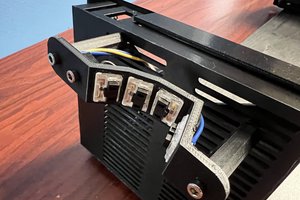
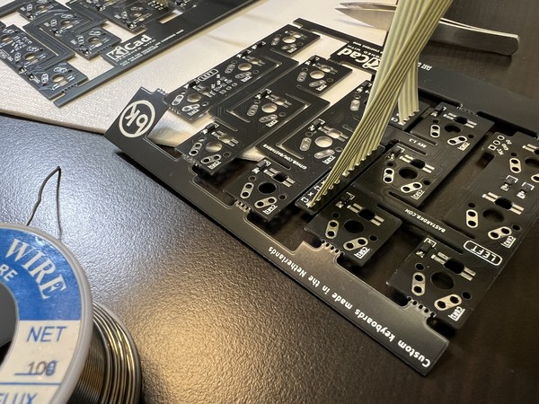
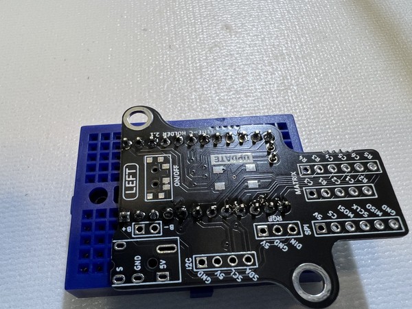
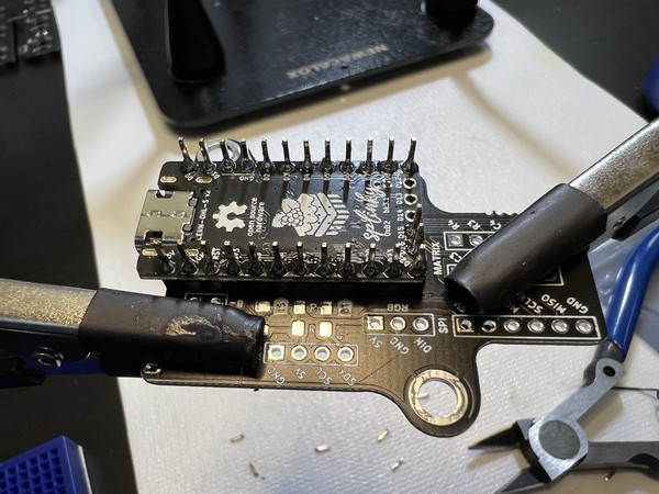
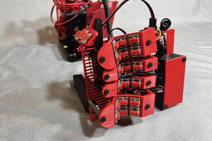
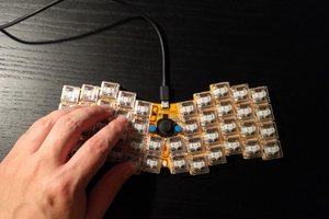
• Finishing the build

    Peter Lyons04/24/2023 at 23:15 0 comments

    I proceeded to solder in the switches unmodified. I found one broken switch on the index finger home row of the second half which required removing the MCU holder to desolder it and replace it with a working switch. But other than that things went OK. I was able to exceed 80WPM with good accuracy with a minute or two of setting up my keymap which is great. I don't love the switches due to the travel and noise, but I don't hate them. I'm glad they are linear and medium-light spring tension.

    Most of the final details got written up into the blog post about this build.

  • BB Mod Backfire

    Peter Lyons04/23/2023 at 14:06 0 comments

    While experimenting with different size ball bearing mods to reduce travel, we didn't have a great test rig set up. I guess ideally you'd have a hotswap MX keyboard at hand and swap in your modded key to do some careful quality control tests. Being low-profile enthusiasts, we have little to no MX gear around here, so our test rig consisted of holding the modded switch in the skeletyl PCB and trying to rotate it where both switch pins would make good contact with the PCB through holes then while not letting that wiggle out of place, try to type. We basically got "it never types" or "it probably types OK" result accuracy.

    We got a nice shot of the travel reduction of each mod by removing the springs so gravity would leave the stem in the lowest position for the photo. The rightmost switch isn't fully seated into the plate. Sorry about that. I didn't notice until I had already torn down the rig. But the 1.5mm ball bearing and 1.5mm hunk of PLA filament both do exactly the same thing to the stem travel.

    So yesterday we proceeded to insert a modded switch into the skeletyl 3D printed case, bend the flexible PCB into position over the post, and solder the first switch into the case. Once that was done, we had a much more reliable setup from which to carefully test for clean typing.

    AC went into production line mode opening switches and preparing to work through a full batch of 18 switches, but I insisted we do a round of careful tests first. It turned out to be the right approach because as we tested, we easily found clear double-press misfires with sometimes as much as like 5% probability. So we kind of panicked a bit and soldered I think 3 total switches in: one stock with no modifications, one with a 1.2mm ball bearing, and one with a 1.5mm ball bearing.

    The unmodded switch worked without issue. Both of the modded switches had frequent double-fire errors. I got pretty despondent and felt like all this time researching, ordering, waiting for parts, 3D printing custom tools, etc was  a waste. I mean, we learned what doesn't work though, right?

    So then I had to desolder the modded switches so we could unmod them. I got them out but desoldering is tricky business.

    So next there was like a camera pan to a high overhead shot of me in the lab where this project was supposed to yield a choc skeletyl and instead here I am building with unmodified MX switches with a mile of travel and a super high profile like a pleb. So I decided to just finish the build, play around with vial firmware which I haven't used yet, and try it out. If it's OK for me to type on, it will be in theory less janky than my current daily driver hand wired tbkmini.

    Getting the switches installed, clicked into the "flexible" PCBs and soldered on a skeletyl is hard. Like really hard. Like, it would be easier to hand wire this hard. The "flex" mechanism doesn't really handle the z-axis variation that well. I bent switch pins on a bunch of switches in trying to get the PCB pressed into place.

    Eventually I found solutions combining helping hands clamped to the case, and either a tweezer wedged in holding the PCB down or a spring clamp if there is access from the side to place it.

    When I got one side finished, I mounted the MCU holder PCB to the case. This was also very tricky to get both ports fully aligned with their holes in the case and both of the threaded inserts exactly below the through holes so the screws can thread in. I eventually got it to work, but this could easily have been 15 minutes of futzing.

    When I went to attach the bottom plate, I had another sad trombone moment when I realized I had soldered the ribbon cables to the wrong side of the MCU PCB. I think the electronic connections are still right because the legends lined up, but there's also a chance that the wiring matrix is now messed up and I'll have to adjust the firmware to compensate for that. But in the end, I just bent the ribbon cables a bit closer to the...

    Read more »

  • BB Mod Experiments

    Peter Lyons04/16/2023 at 17:47 0 comments

    So we've been exploring whether to complete the build with MX switches which are what the skeletyl case and PCBs actually support, or hack some chocs in there with some extension wires. For now, we're pursuing MX switches with mods to make smallest activation travel and quietest operation. I bought some akko custom switch silvers which are 3-pin linear MX compatible switches. The springs feel fine but of course the stock travel just feels comically large.

    To reduce the travel we've been experimenting with [the ball bearing mod](https://imgur.com/a/xmSVZ). I bought some ball bearings in size 0.8mm and 1.2mm. I ordered some 1.5mm but they haven't arrived yet. We also snipped off a 1.8mm brass sphere from a keychain.

    We did a bunch of tests.

    * 1 ball bearing  0.8mm does reduce travel and the switch still works

    * 1 brass keychain ball of 1.8mm does reduce travel but too much so the switch never activates

    * 1 ball bearing 1.2mm does reduce travel and the switch still works

    * 8 ball bearnings 0.8mm (yes we put 8 in a single switch) does work and the switch still types

    * We carefully cut a piece of PLA 3D printer filament to exactly 1.5mm and dropped that in and it works

    * 2 ball bearings 1.2mm makes the bottom out crunchy

    We are waiting on supplies but our hypothesis is that a combination of o-rings and 1.5mm ball bearing will probably be our best result for shortest travel while still activating consistently and quietest operation.

  • Research oopsie

    Peter Lyons04/11/2023 at 23:58 0 comments

    Well I was all ready to plug my choc silver switches into this thing when I realized they don't fit. I double checked the bastardkb site and sure enough, it's MX format only. I tricked myself because I built a tbkmini which is basically the same as a skeletyl plus one extra column, but since it's handwired I was able to use kailh choc switches.

    So, I debated what to do but ultimately decided to order some akko silver silent speed switches and ball bearings so I can mod them for lower travel and solid bottom out. We'll see how it goes. Gear should arrive Friday so hopefully I can do another build session this weekend.

    I was not expecting to go back to MX switches after being on team choc for so long, but maybe with the ball bearing mod the travel will be even less than a choc switch.

  • diodes and ribbon cables

    Peter Lyons04/08/2023 at 22:18 0 comments

    I got the case 3D printed on a friend's printer while traveling this winter and had the electronics kit waiting for me at home. I bought it since I won a coupon in a raffle by kbd.news.

    I started the build today and got the heat-set threaded inserts in no problem. I use these all the time in my personal projects so I'm very comfortable with them.

    I arranged the PCB parts to keep track of left/right more easily.

    Next were the very tiny T4 surface mounted diodes. I've done a bit of surface mount soldering before, but nothing quite so tiny. I started out using a magnifying glass but eventually my eyes adjusted and it was easier to do without the magnification.

    After all the diodes were on, it was time for the ribbon cables. I wasn't aware of this type of cable. It's basically some flattened wires with masking tape. It's pretty clever and tidy though.

    Here they are soldered into the board.

    I also hadn't used these "mouse bit" breakaway sections so I was nervous but everything worked as designed.

    This kit has some clever daughter boards for the slinky microcontroller, and those came next. I think if I screwed up this step, it's game over.

    I got the wires interconnected and called it a day for day 1. Tomorrow I'll work on the switches and cases.