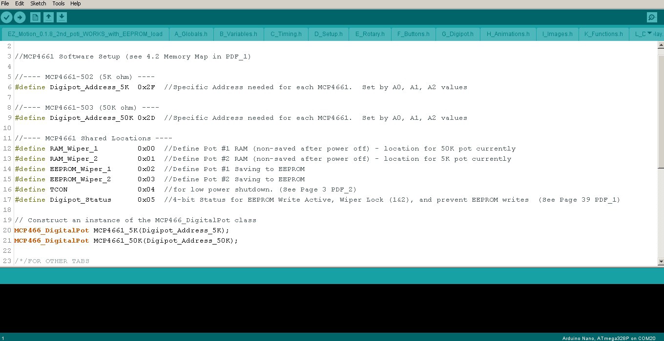
 CriptasticHacker
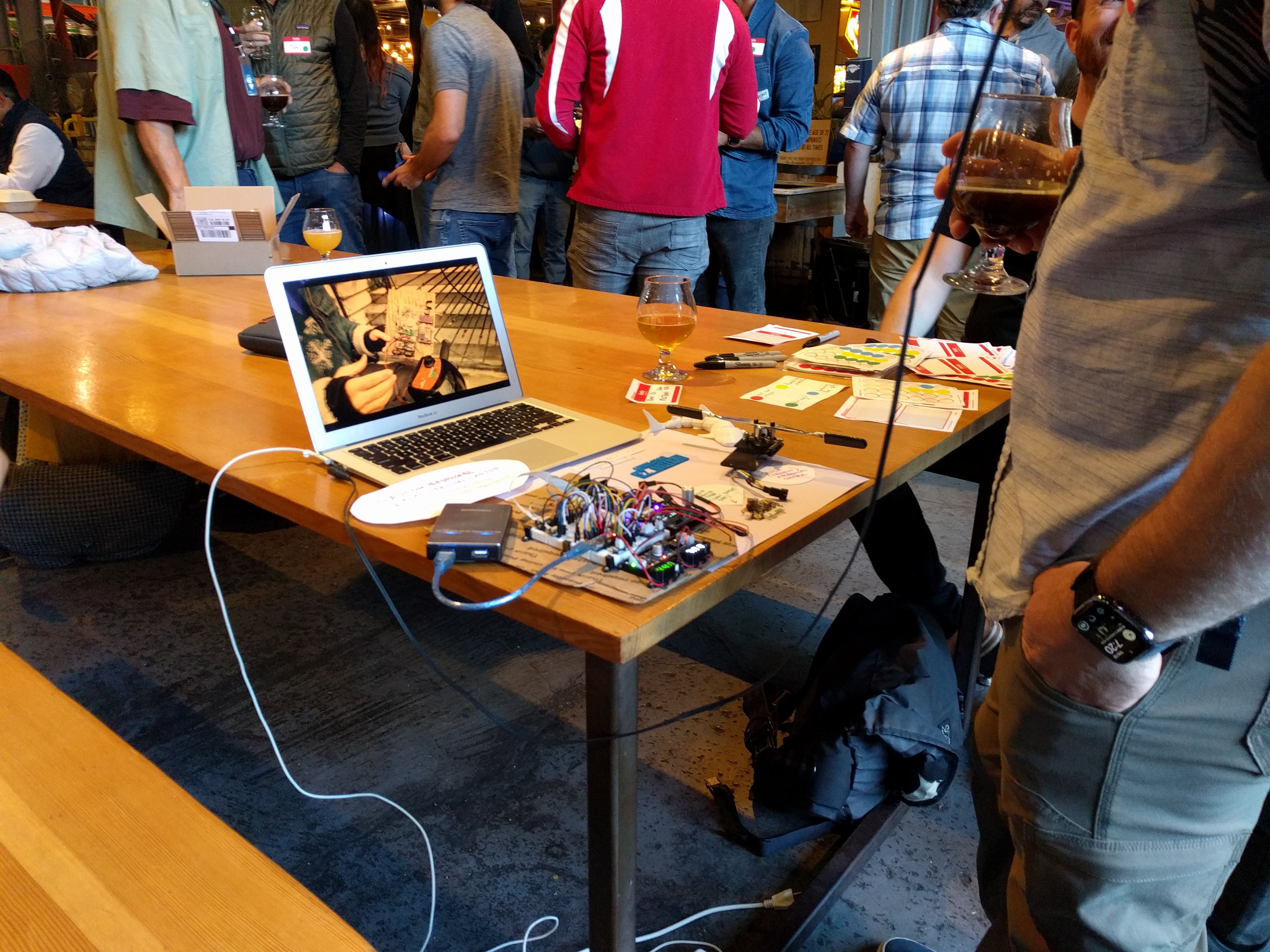
^ First DEMO VIDEO to show current project progress!
*** Please check out the Project Logs - that's where all the best stuff is! :)
NOTE (2-2024): This project is currently shelved until I can get some funding or support to finish it
if you(!) or anyone you know is interested in supporting it, feel free to drop me a message here! Would love to hear from you :) You can message me here or at criplishus [at] gmail
-- The P R O B L E M --
This project was born of necessity, as I have hand disabilities in addition to being crippled. Manufacturers of DME (Durable Medical Equipment) do not often seem to consider the scenario of multiple disabilities or get much feedback from our community, as these devices are:
1) painful to operate / extremely uncomfortable
2) closed-source, with almost non-existent parts and support
3) have high mark-up (on the assumption that all cripples have insurance - we do not)
4) Use 1990s technology with little to no innovation
-- The S O L U T I O N --
I am going to show these DME industry people how to do it right - and hopefully inspire others to take our valuable feedback as disabled customers to create innovating, exciting, and (dare I say) comfortable solutions :)
There's a lot to fix on modern electric wheelchair and scooters, but I am going to set my sights on creating a more accessible motion control mechanism.
-- B A C K G R O U N D ---
Wheelchair Types:
There are 2 basic types of electric (a.k.a. motorized) wheelchairs. Let me describe them:
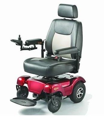
1) The "Power Wheelchair" has 2-wheel drive, 4-way motion system. These are upright chairs with 2x passive caster-type wheels in the front, and are designed to be as compact as possible. They are primarily for short-range movements, and meant for people staying indoors. These chairs usually employ a multi-directional analog stick control, and similar to a video game analog control stick, have built in springs for each direction to return to the home (center / off) position.
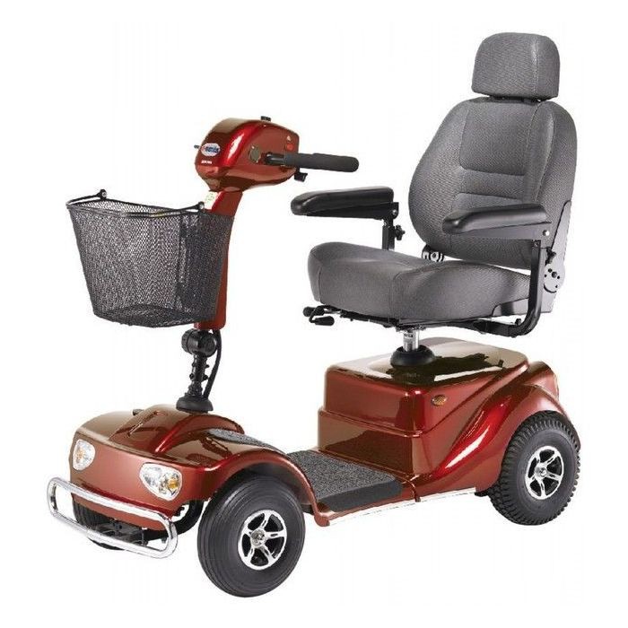
2) The Wheelchair Scooter, a.k.a. Mobility Scooter, is a much larger device, usually with a single transaxle motor so that motion is only bi-directional, requiring the user to steer left or right by moving handle bars (like a regular bike). Only one wheel is actually driven by the motor, making these easier to get stuck sometimes on elevated platforms like curbs or bumps. The steering of the user changes the forward or reverse angle, not the motors, which means a much wider turning radius. In exchange for this, these wheelchairs are often lighter, less expensive, and can travel farther - used for going to stores or events. If you are in a modern city, these can often still fit on buses, too.
-- T H I S P R O J E C T --
I'm going to be hacking / upgrading my wheelchair scooter (#2 above), due to:
1) Personal need
2) Ease of modification
3) Easier reproducibility
4) More uncomfortable (and thus, more need to fix!)
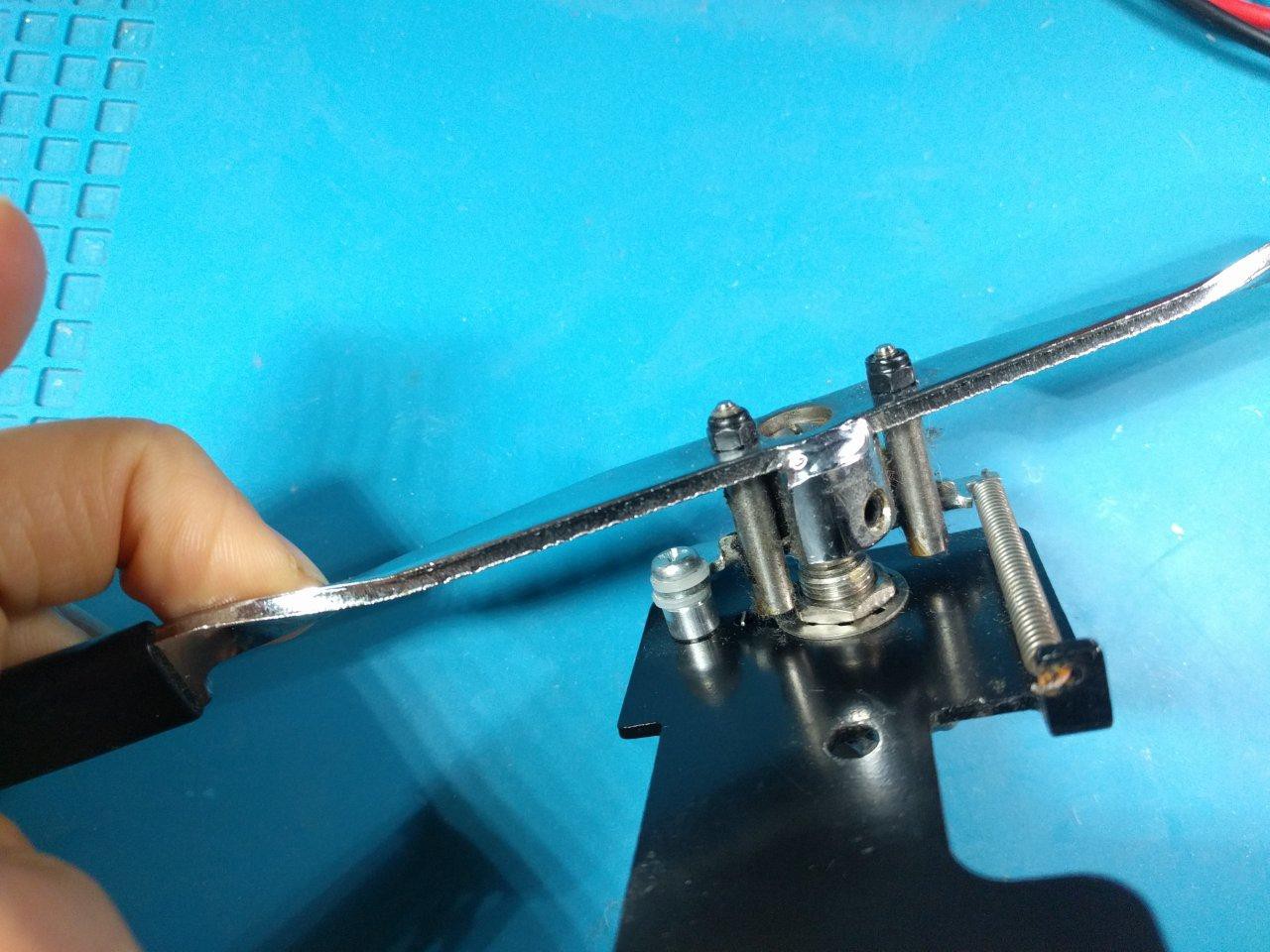
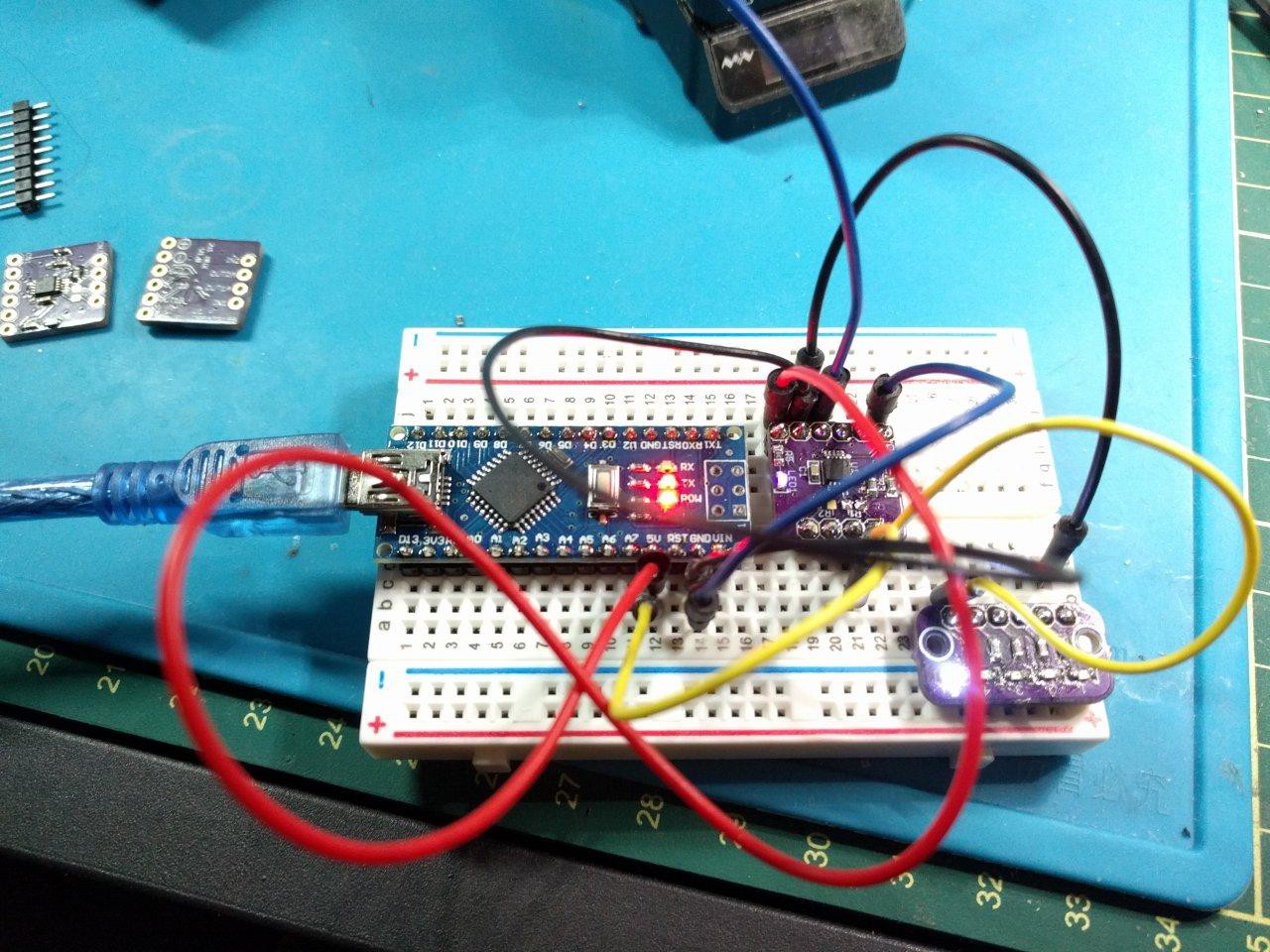
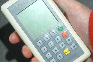
The first step is to learn about the stock motion /user control mechanism. It is a single lever designed as a bi-directional "throttle" (forward and reverse) by turning a mechanical potentiometer which is in the center of the lever:
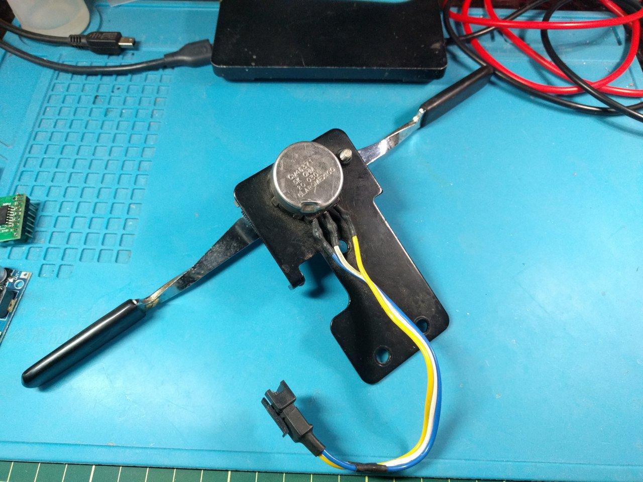

The potentiometer is a 5k ohm "industrial" pot, part # CM46371 by Honeywell. It's a bit mysterious without a datasheet I could find (even on Mouser) and our good friends at Monster Scooter Parts have marked it up to a whopping $35.99(!) This is the only resort for poor cripples trying to fix their wheelchairs....although this page may have some in stock if you're lucky.
-- STOCK CONTROL REVIEW --
(The Problems)
This control device has always felt akin to some kind of torture machine to my hands as well as my wallet.
One needn't look far to see the engineering flaws that are present here:
1) A single high tension spring to provide lopsided control. A sensible design should...
Read more »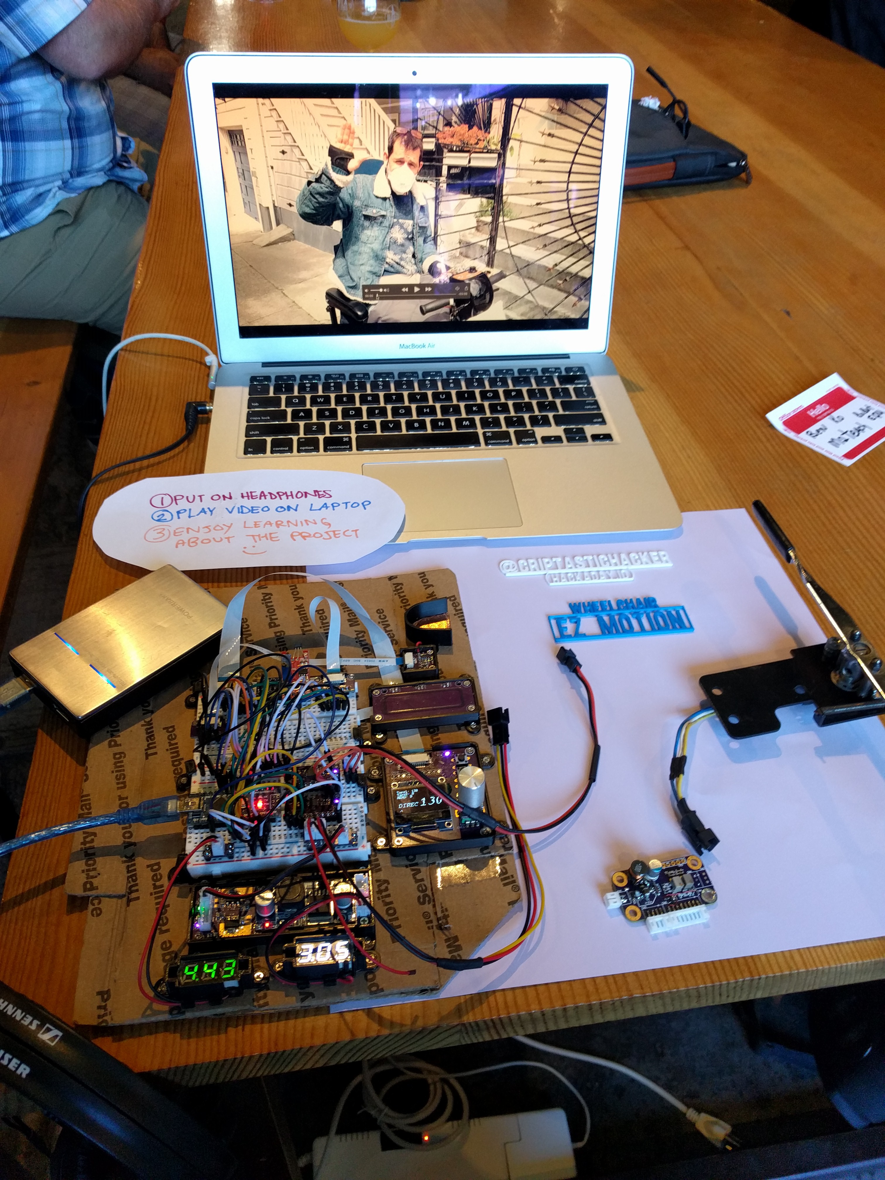


 Boz
Boz
 Jarrett
 Bob Baddeley
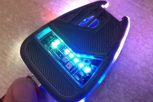
 Xasin
Xasin
can You put Your device to retropie linux for arcade game? for example tempest https://archive.org/details/arcade_tempest