 CriptasticHacker
The TTP223 slider control and single touch PCBs came out beautifully - on the first iteration :) See my post below for more of the details and the reference design. Capacitive touch is so fun to work with and (when done right) is incredibly responsive and bug-free! and so much less painful to use.
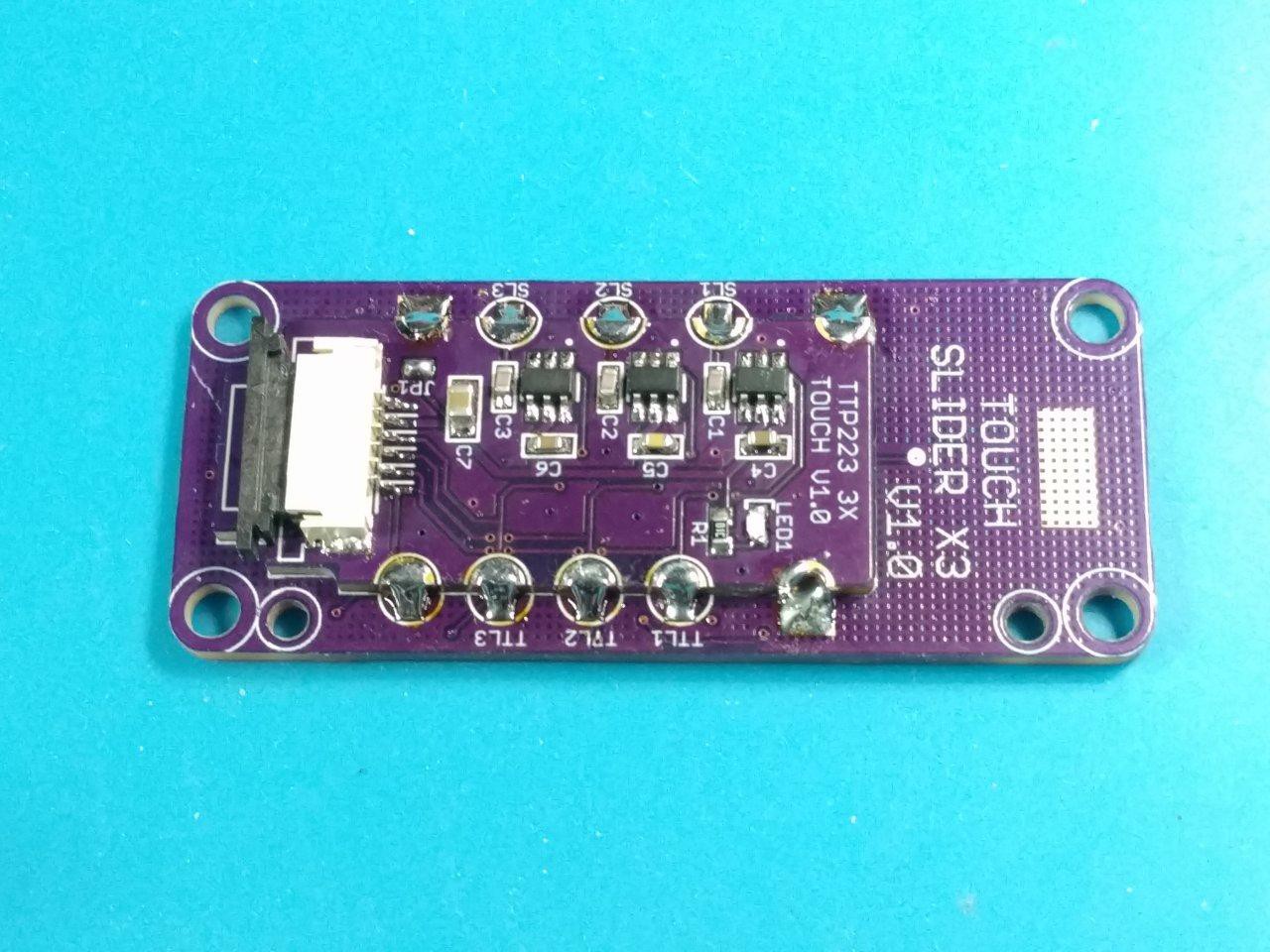
The castellation design worked out perfect - 3x duplicate TTP223 modules. This modular design allows me to reuse the slider touch PCB with a different IC, or the ESP32's touch GPIOs later. The FPC-6 1.0mm connector is nice and durable and makes cable management and mounting a breeze :)
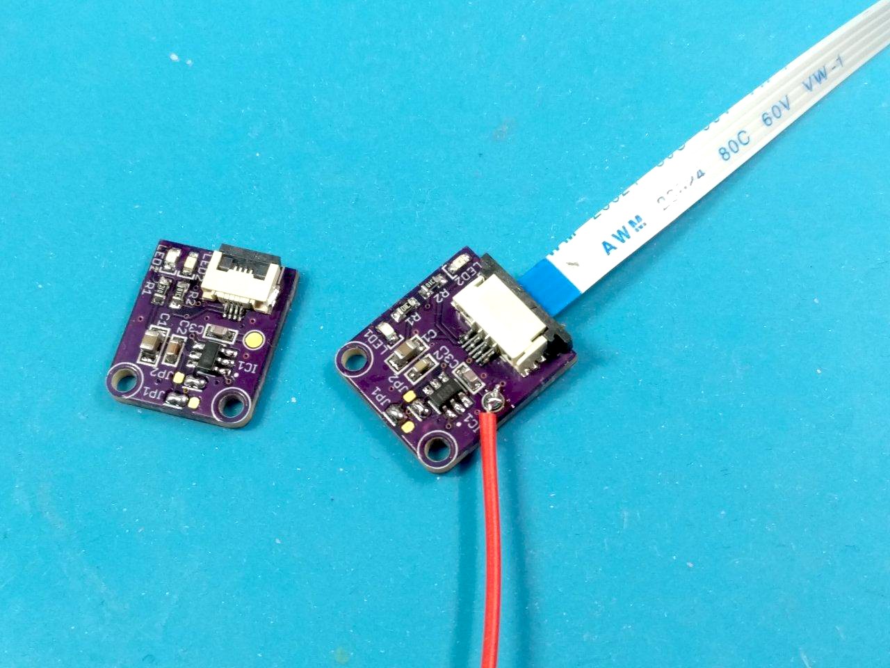
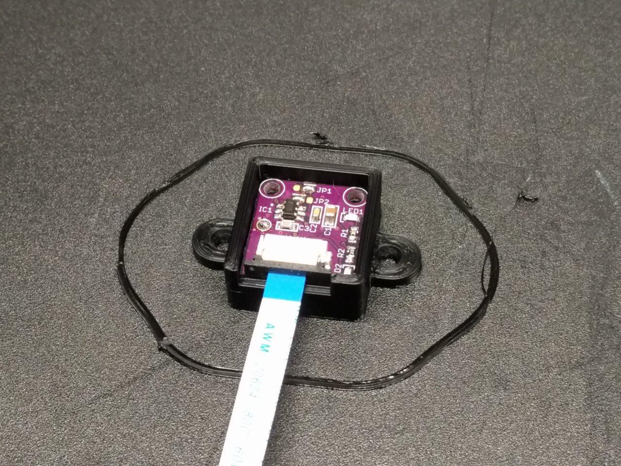
The next PCB I assembled was the single touch version. As mentioned in my previous post, I wanted to have more features than the cheapo ones that are already available. I also prefer the flexibility (no pun intended) of using Flat Flex Cables.
Unlike the slider, I did not design a special touch PCB for these. The red wire goes to a piece of copper for the touch sensor. I found that this (not surprisingly) made the triggering a lot easier to do, as there wasn't the surrounding ground plane or the hatched ground underneath to break up stray capacitance.
In order to keep the copper from triggering too easily, I changed the parallel touch capacitor from the frequently used 22pF value to a higher range of 47pF. the datasheet for the TTP223 mentions that higher values reduce sensitivity, and this worked like a charm. Problem solved.
Now it's time to 3D model and print a panel mount case...
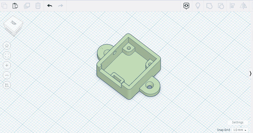
Took a couple iterations to get the FFC cutout and support, but it's solid now!
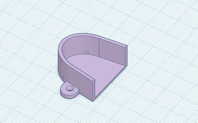
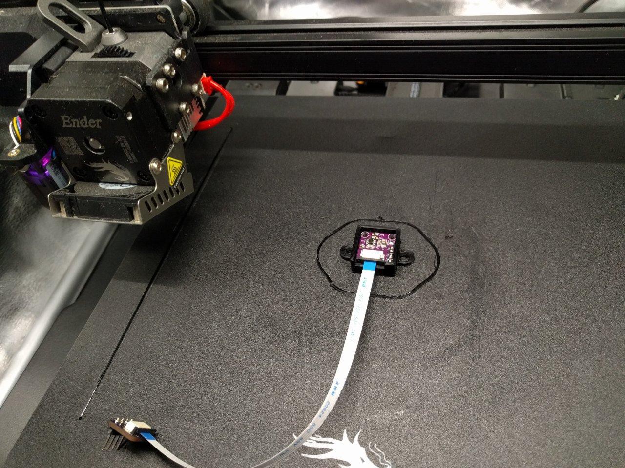
Then I had some fun making a 3D model to match my actual thumbprint. I love stuff like this - I thought this is the kind of customization that disabled people deserve to have with our medical aids. and why not? I took measurements, modeled, and 3D printed this in about an hour :)
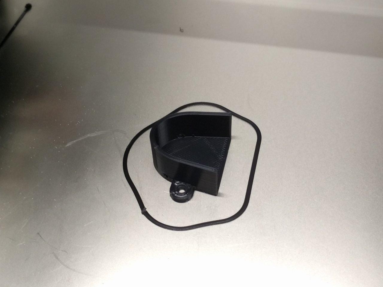

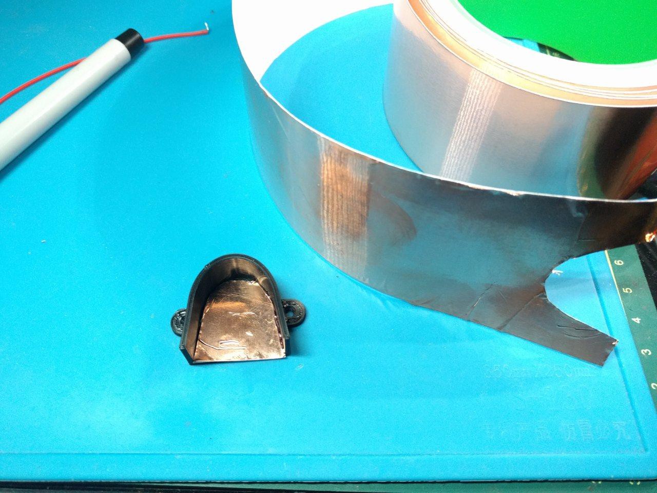
Here you can see I used the roll of adhesive copper foil to cut out a matching touch sensor. It's crude, but it does the job! I also modeled the case to have holes in it for the attaching wire.
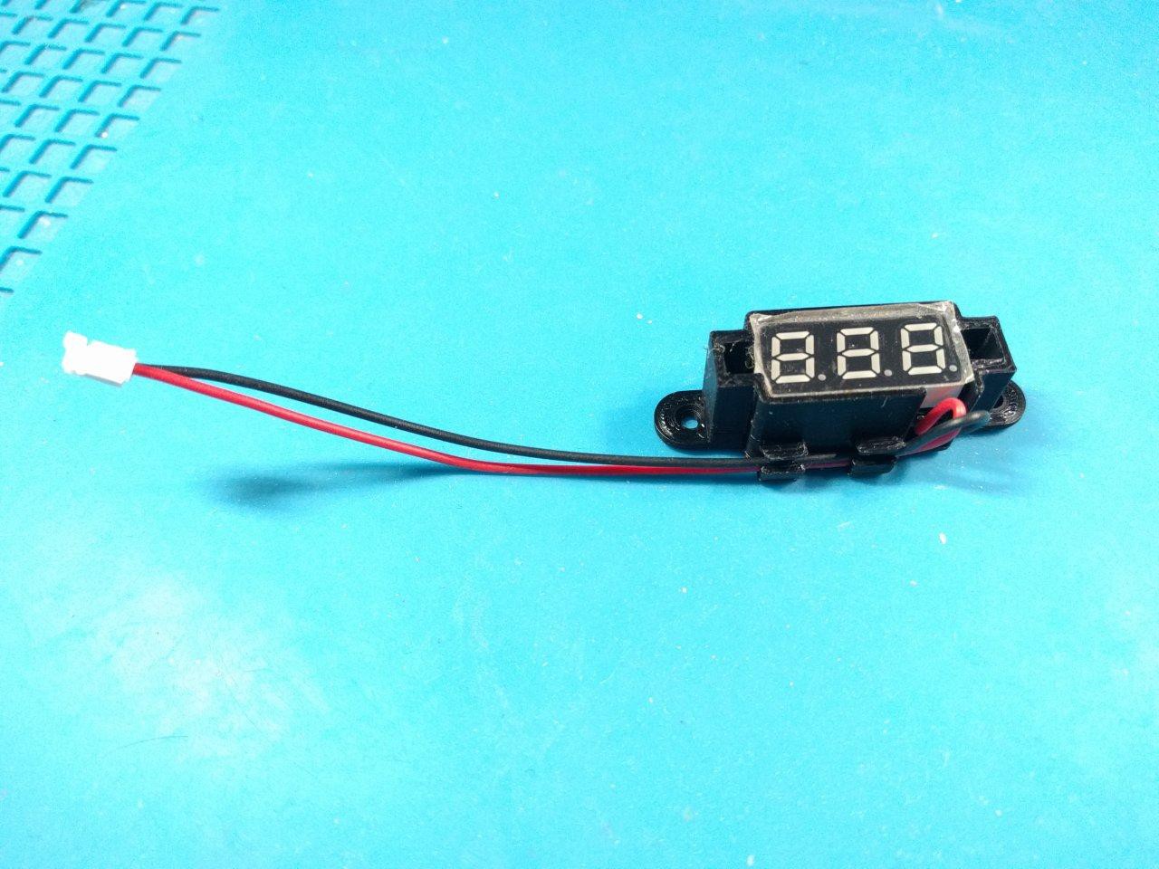
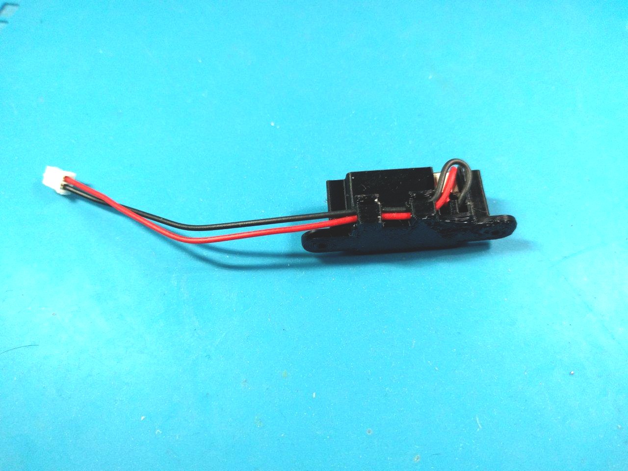
After this, I updated my LED voltmeter case. It's also a panel mount now, with a nifty cable strain relief as well :)

With that done, I realized I needed some panel mount brackets to lock in my testing breadboard. Sure, it has a big slab of adhesive on the back, but I try to avoid hard to remove adhesives during prototyping whenever possible.

Now it's time to assemble this funky set up... Ideally I'd use a piece of plywood to screw everything into, or an enclosure case of some sort. I didn't feel like 3D printing a huge case that I will grow out of in a week of R&D. And I was feeling too lazy to take out my miter saw to do plywood cuts, so...
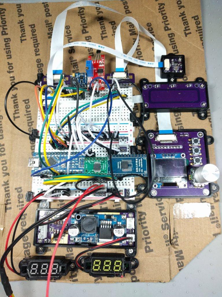
The entire thing is assembled on two layers of cardboard - USPS flat rate cardboard! Free at the post office ^_^ my M2 wood screws threaded into it surprisingly well....now, it's time to update the firmware...
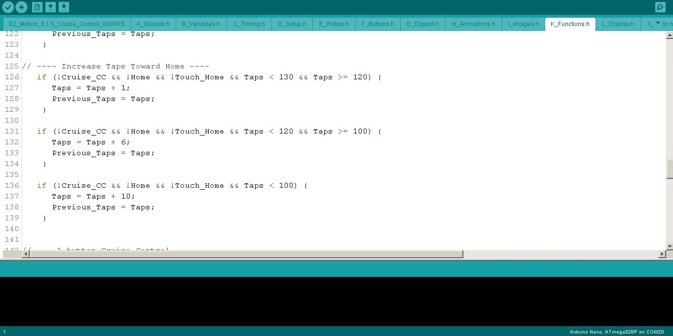
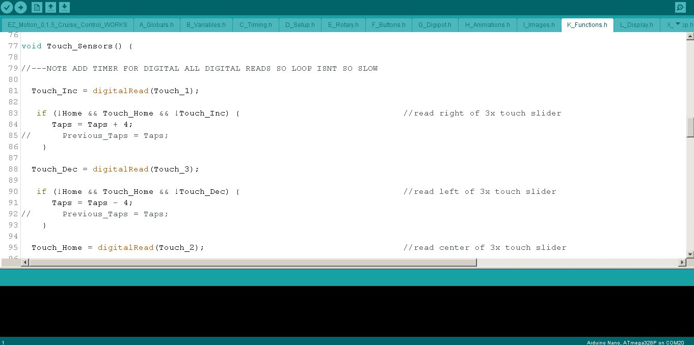
Nothing too fancy here - added some new globals for the touch I/O and variables [not shown].
The copper foil touch sensor definitely benefited from some denouncing, which took a little bit of fiddling with to get the cruise control to trigger just right. It works *really* nice now...
The slider code was easy to get working, but will take some time to get it perfected. I'm just guesstimating how much the pot values affect speed. It's logarithmic though, not linear, so it's a spotty business. I have to give it some TLC later on, although I'm hoping I can avoid a lot of the work by simply adjusting acceleration with the rheostat dummy load to another digipot (more on that later).
...Now it's time to take it for a spin! ^_^[to be continued...]
Discussions
Become a Hackaday.io Member
Create an account to leave a comment. Already have an account? Log In.