 DIY GUY Chris
In this project, we will discuss how to create a Logic Gates Training Board, which we call the LOGIX. The LOGIX is a circuit board that can receive any logic gate and produce an output signal based on the used gate. We will explain how each of the most commonly used logic gates work and demonstrate how they can be combined to create more complex circuits.
Supplies
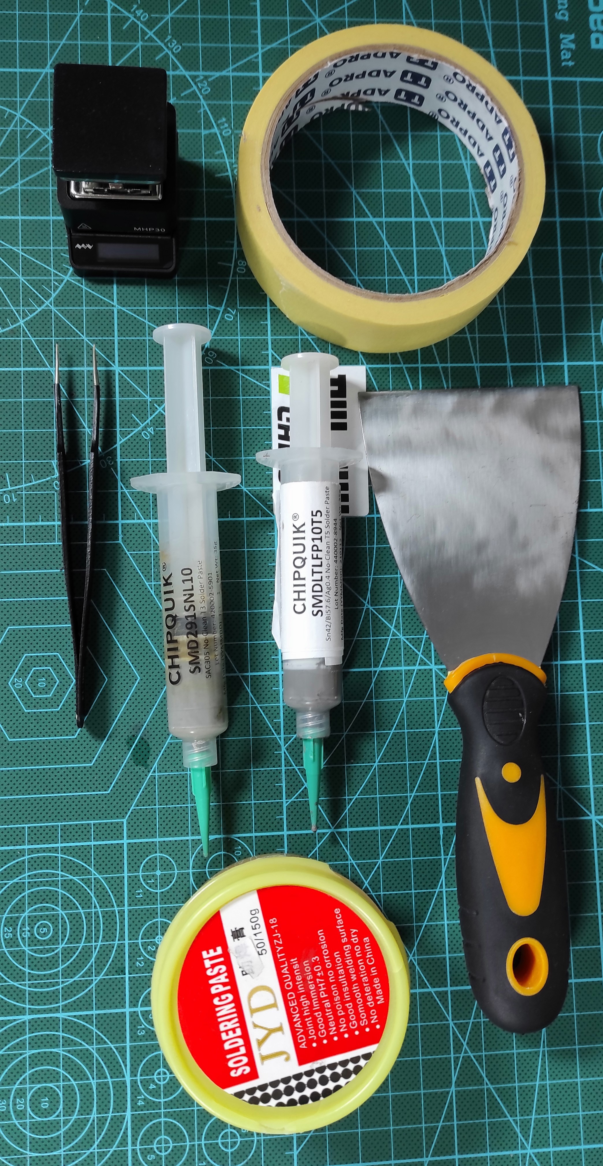
I designed and Assembled the LOGIX in my home-lab so if you wan to follow the same process then you may need the following tools:
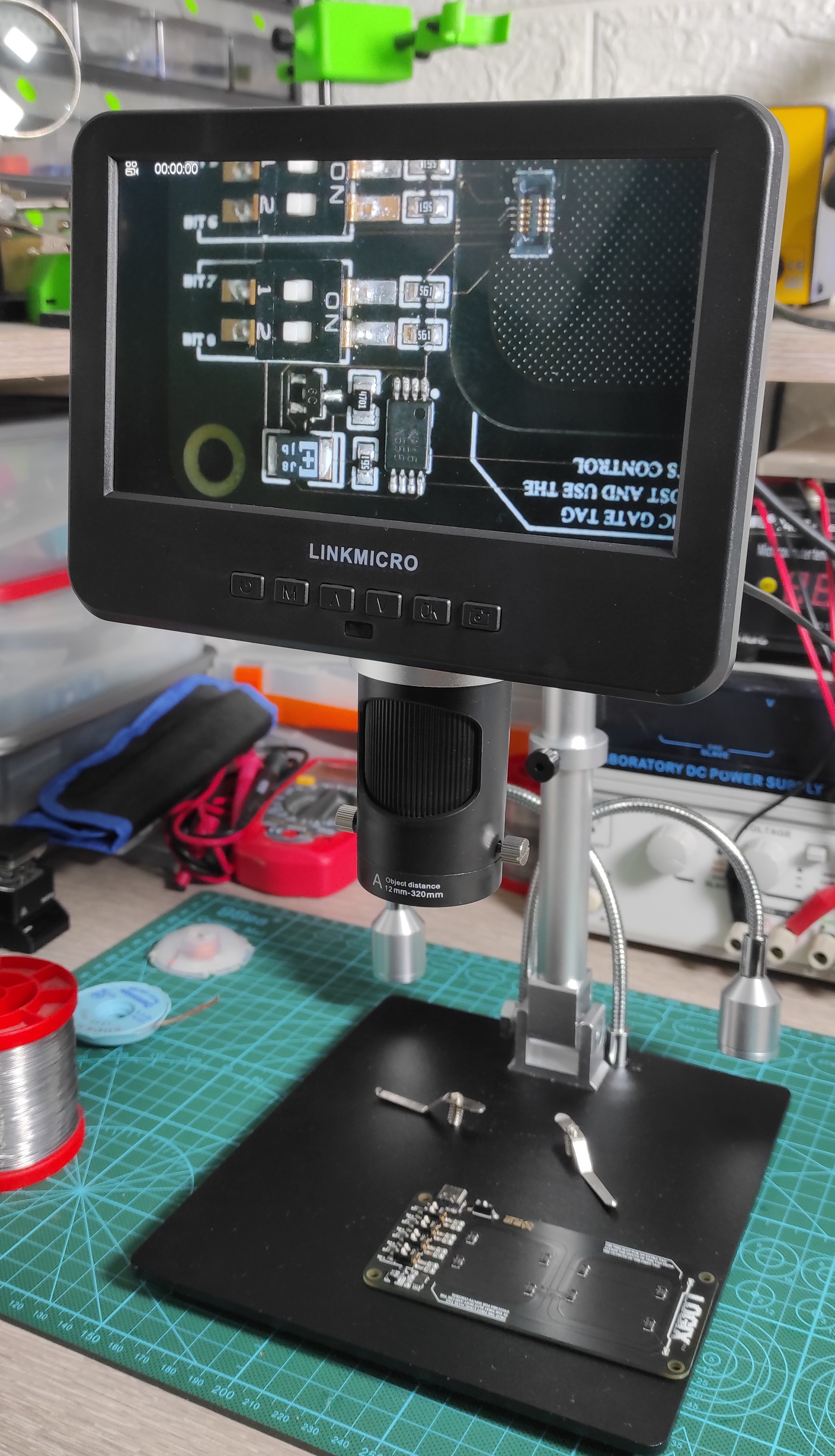
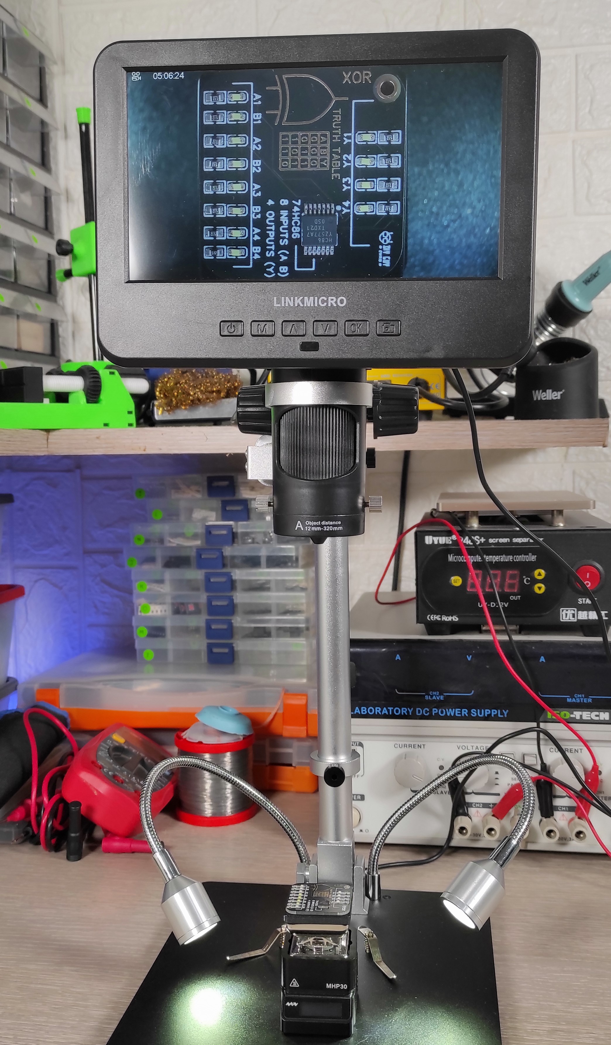
- Digital Microscope Camera LINKMICRO
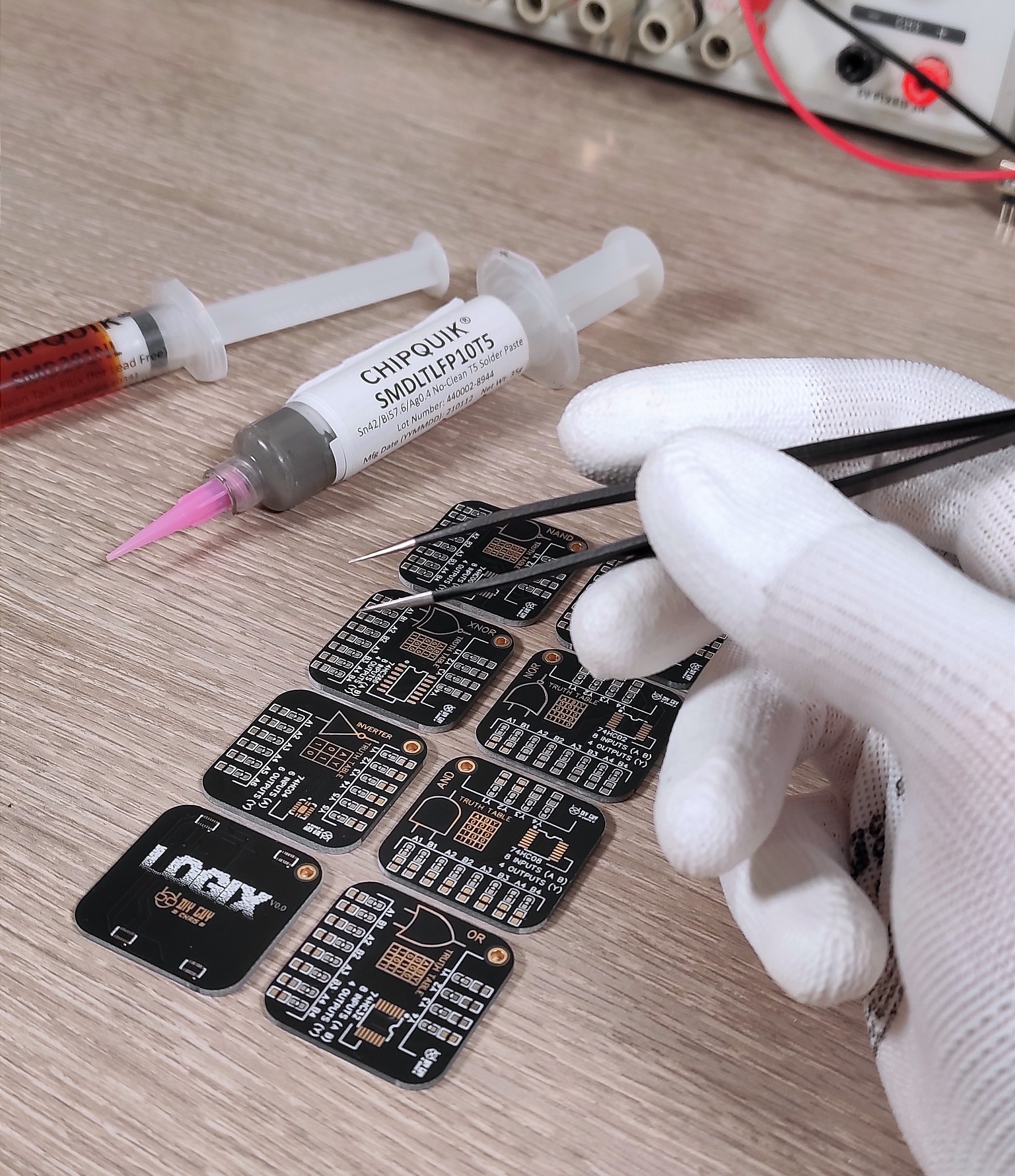
- Solder Paste CHIPQUIK SMDLTLFP10T5
- Flux removal Solvent
- Tape
- Spatula
- Hot Plate MHP30
- Solder Iron Weller WE1010NA
- Precision tweezers
Circuit Design
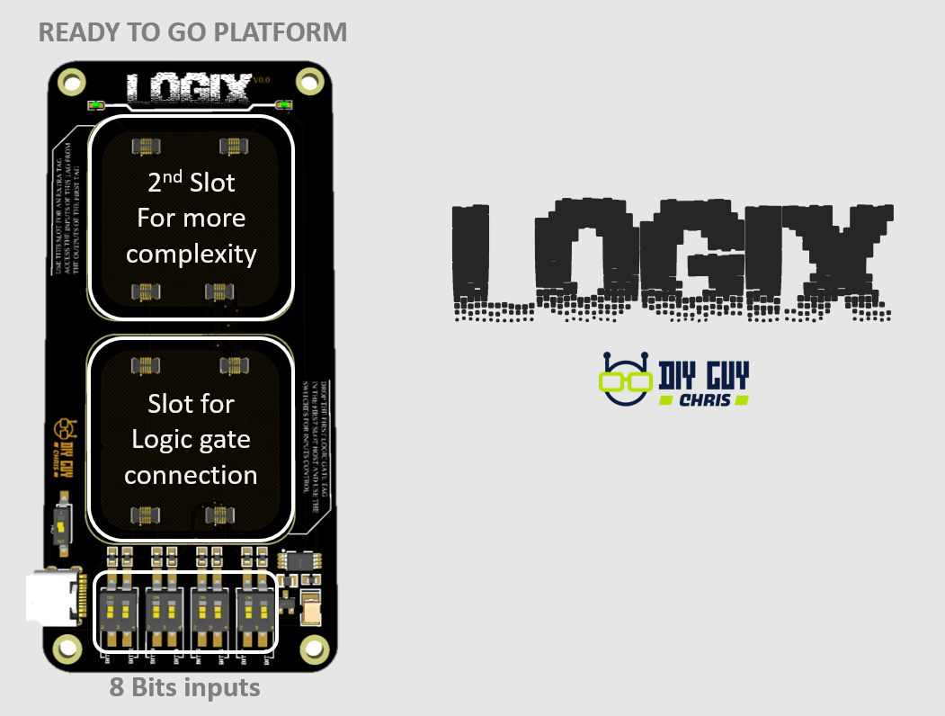
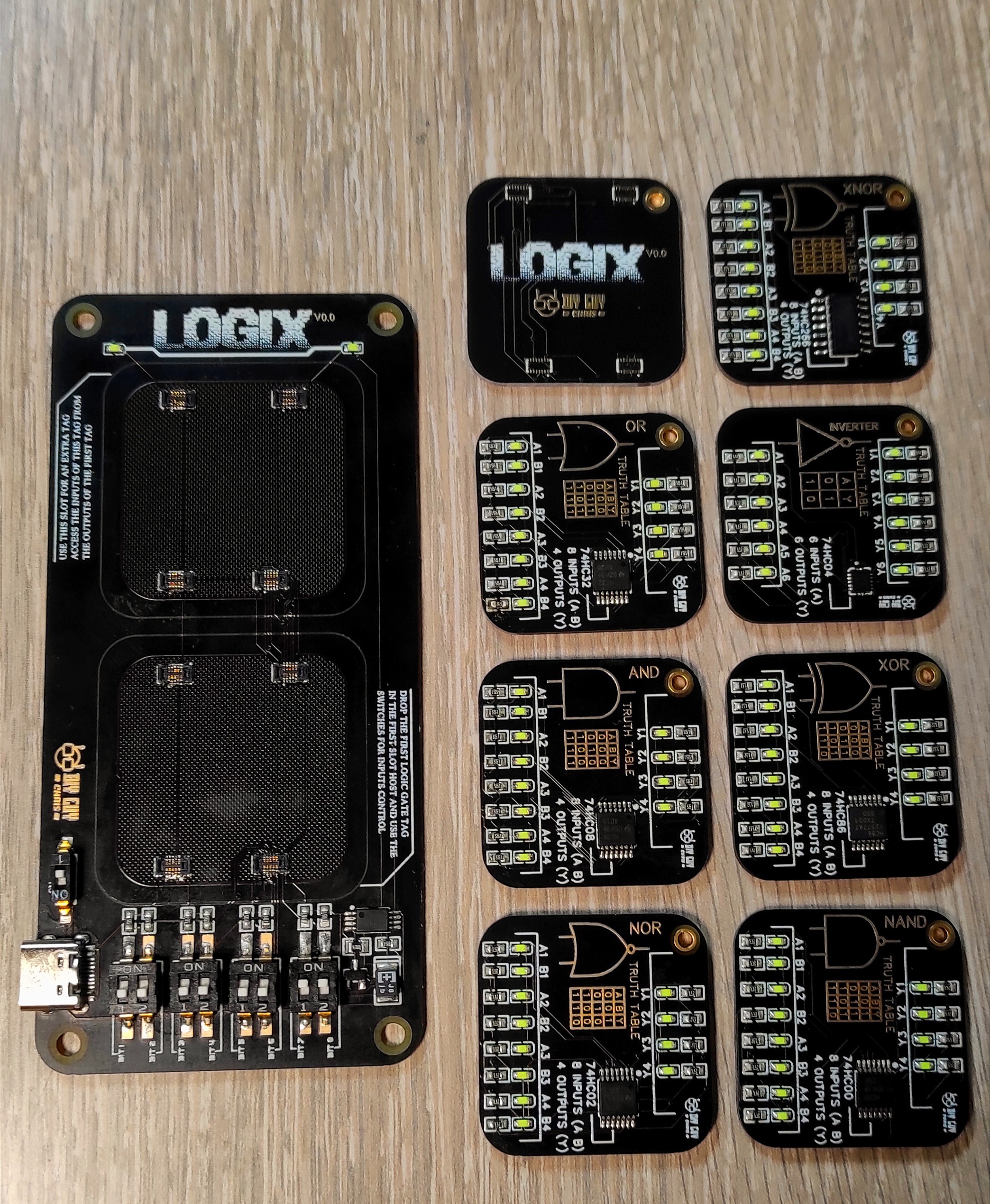
To create the LOGIX Master board, we used Altium Designer. The master board has eight bits inputs connected to slots where we can connect another small circuit board that has the logic gate. This way, we can connect the input switches to the gate, and the master board has a second slot where we can connect a second gate. The inputs of the second slot are connected to the outputs of the first slot, allowing us to combine two logic gates to produce a more complex circuit.
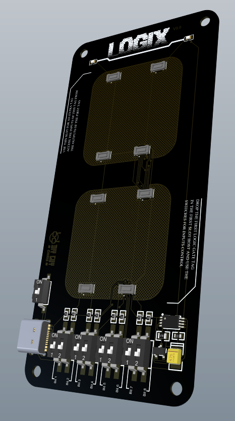
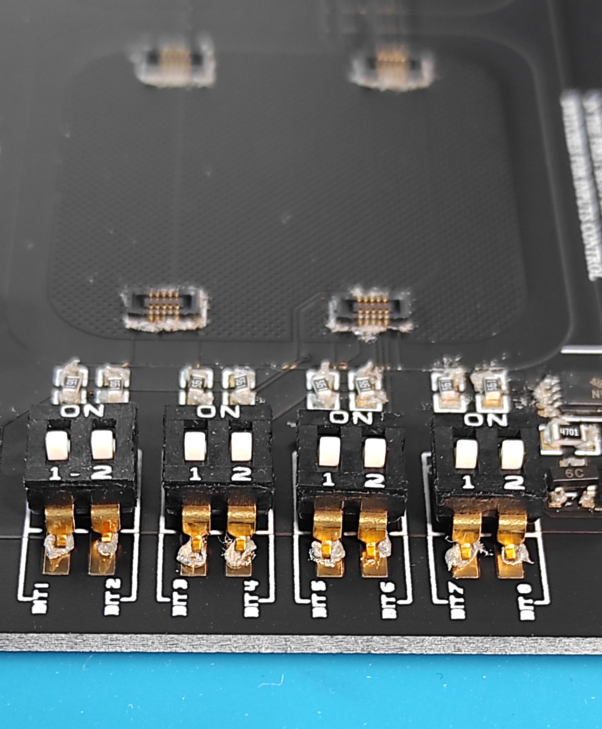
We needed four mezzanine connectors at each slot, so in total, we used eight connectors. We placed a USB C connector for power supply, a power on/off slide switch, and four slide switches for the eight bits inputs. To make the Master board look cooler, we added an NE555 IC to produce a breathing light of the two LEDs as soon as we power on the Master board.


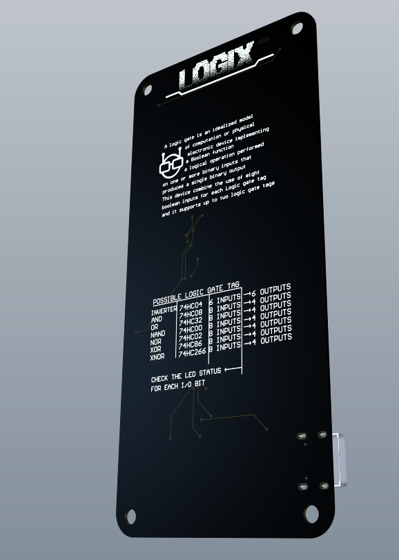
To create the logic gate stamps PCBs, we got all 7 logic gate IC CAD files from Octopart. We introduced LED inputs and outputs indicators to each tag, which helps to display the current logic combination. Each tag has 4 mezzanine connectors, and we set all the pull-down resistors, the LEDs, and the logic gate to the top layer, and the mezzanine connectors to the bottom layer.
Circuit Assembly
We then generated the design-related GERBER files and placed a PCB order from JLCPCB alongside the logic gate stamps PCBs.

After six days, we received a big box containing the Master board and the Logic stamps. We then applied solder paste to all the exposed parts' pads and placed the components.

For manual assembly, we always follow the Assembly app offered by Altium 365 to avoid any soldering mistakes like misplacement or wrong part orientation. We used a mini hot plate to assemble the logic tags and the LOGIX master baord.

Testing the Results
After getting all the components soldered, we cleaned the board using some flux removal solvent. The LOGIX Master board was ready for power test, and the mezzanine connectors were very well soldered.
The LEDs started breathing, and the LOGIX device was ready to receive the Logic stamps and this way we successfully completed the LOGIX Making.
In conclusion, the LOGIX Logic Gates Training Board is an excellent tool for anyone who wants to learn about logic gates and digital circuits. It is easy to use and can be combined in various ways to create more complex circuits that can perform more sophisticated logical operations.

 Ken Yap
 deftcoyote
 JRodrigo
 LorneChrones (Nick)
this is really awesome! where can i download the pcb save to be able to get my own set machined?