Close
0%
0%

Home Robot--What Can It Do?

Using existing robots for guidance, I plan to design and construct a household droid.

Similar projects worth following
"What can it do?"

When I talk about my robots, purchased or homebrew, that question always surfaces. I will discuss a process of developing the design, then following through with construction of a home robot.

Robot vacuums excluded, most "home robots" (Aibo, Cozmo, Loona, Ebo X) fall in the category of entertainment/social devices--meaning they do "party tricks" or provide mobile video/audio services. Manipulating objects is a significant challenge and I plan to open the door to that world.

Purchased robots can be sleek and alluring, but what happens when the unique (not user replaceable) battery fails? What if a gear loses a tooth or a sensor quits sensing? What happens when the app isn't supported or the online service goes dead? Who are you going to call?

This design is modular with large (17" x 17") decks. A class or team can work separately (sensors, voice, arm, power, etc.) while cooperating on the overall device.

Now, Ozzy can talk.

About 65 years ago, "Robert the Robot" entered the world.

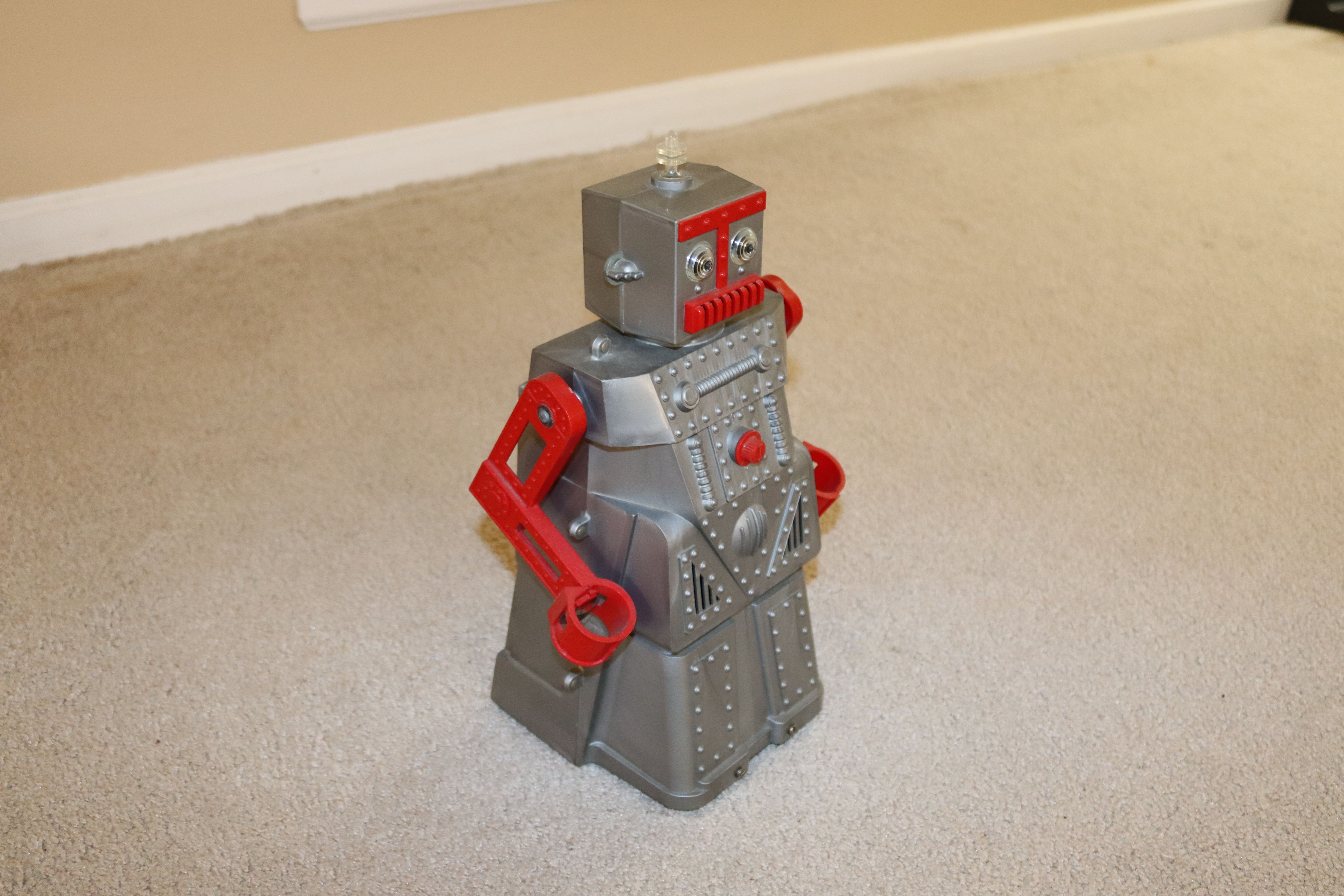
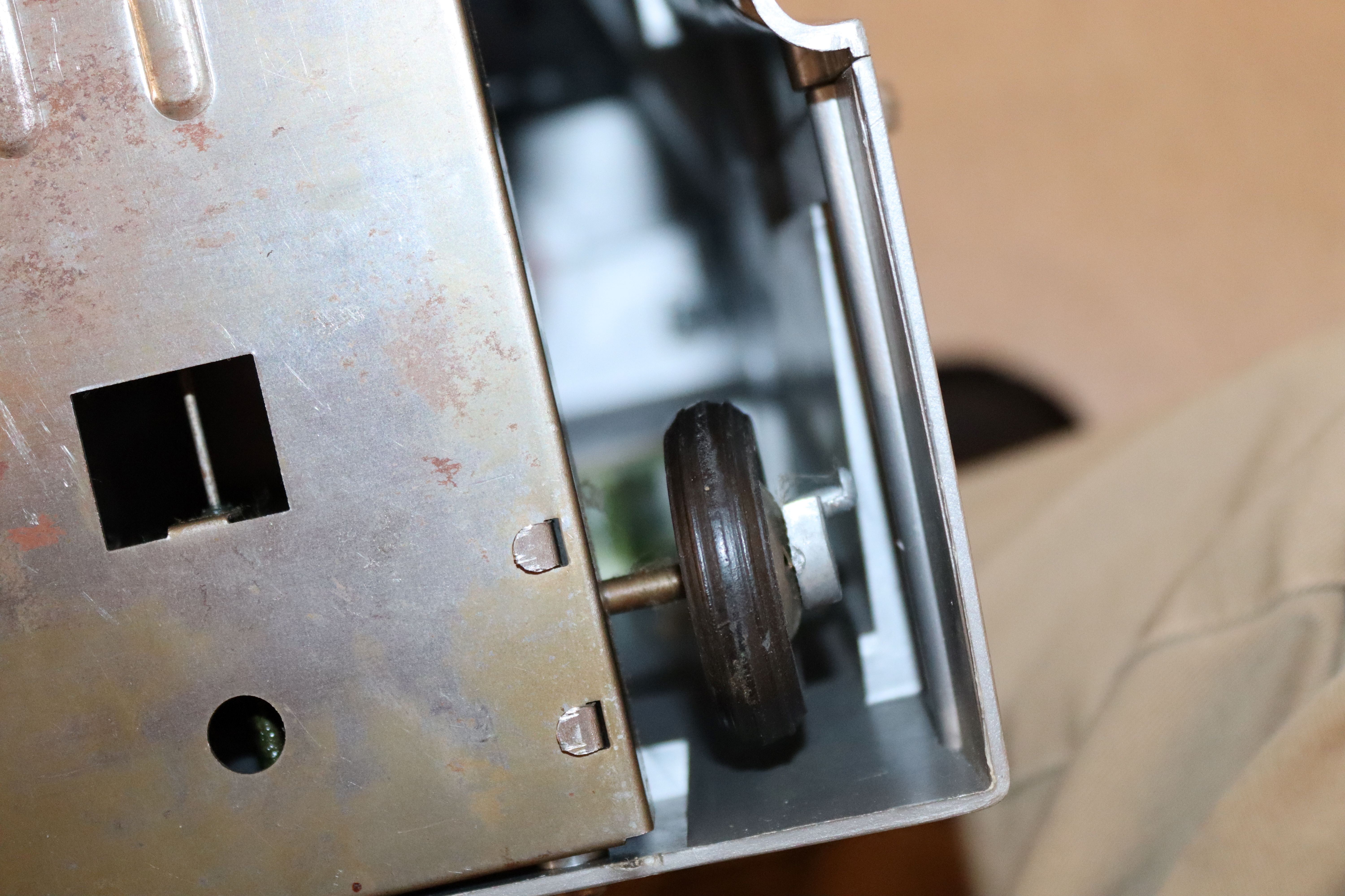
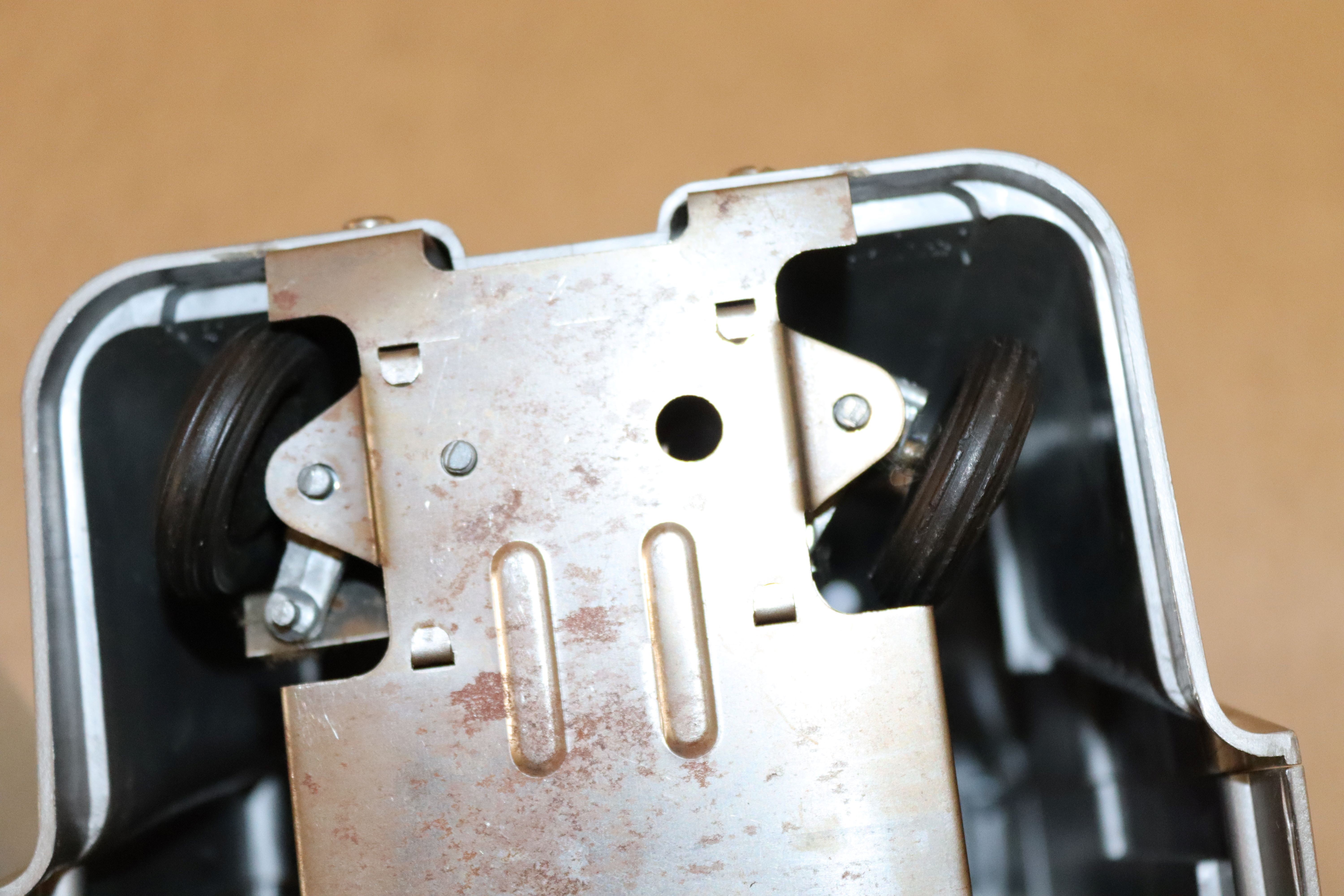
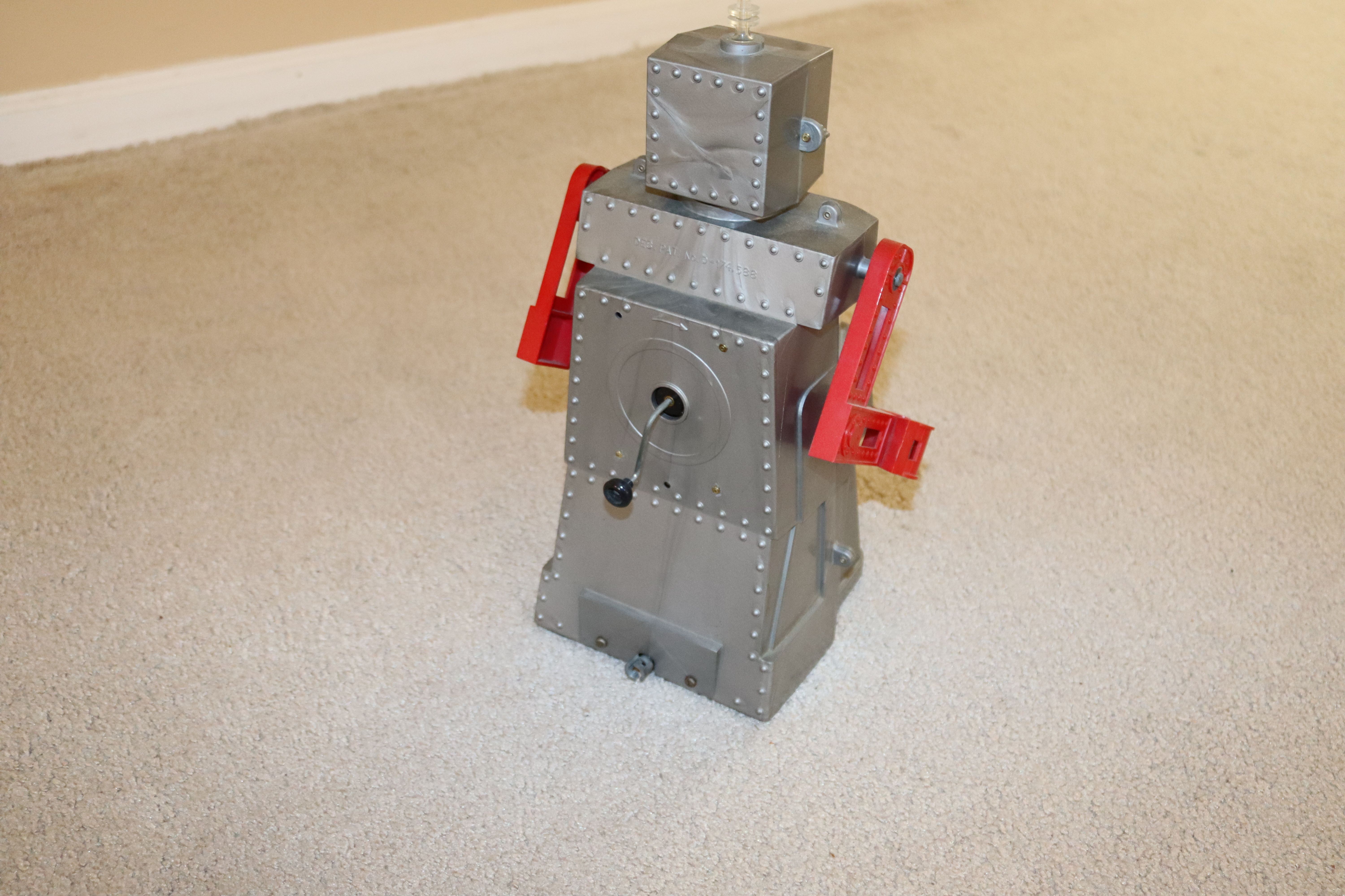
Robert is a remote control toy; moves forward, back, left, right; arms move, head illuminates; he talks.  The "remote" control is a five foot length of steel cables. Forward and reverse motion are controlled by a hand crank that turns a gear mechanism for the rear wheels.

The rear wheels are connected by rods to the arms.

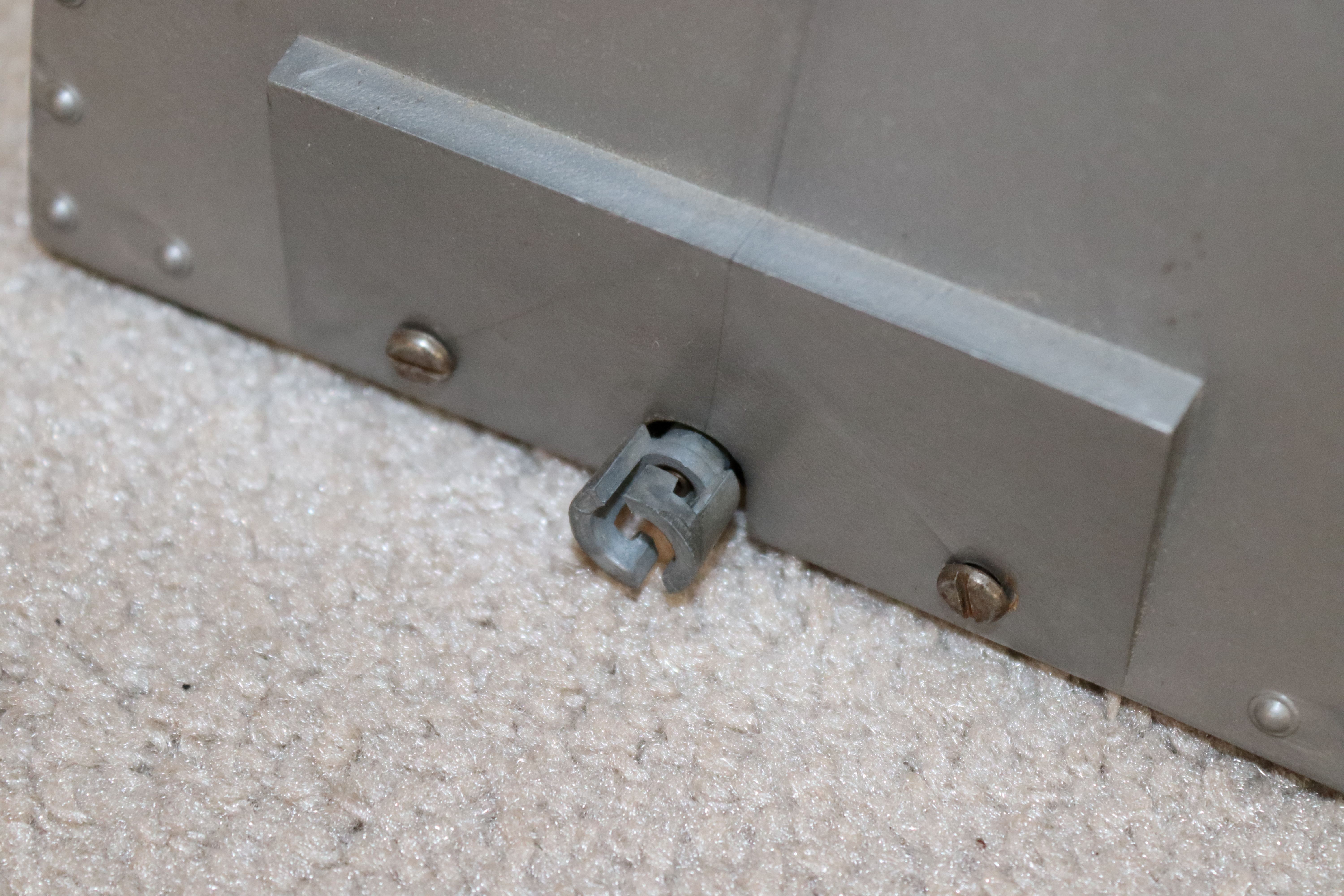
Steering is managed using a pistol grip on the controller. The front "steering" wheels are spring loaded to one side. Pressing the pistol grip changes the position of the steered wheels.

The light in his head (operated by a D cell battery) is switched by a knob on the front.

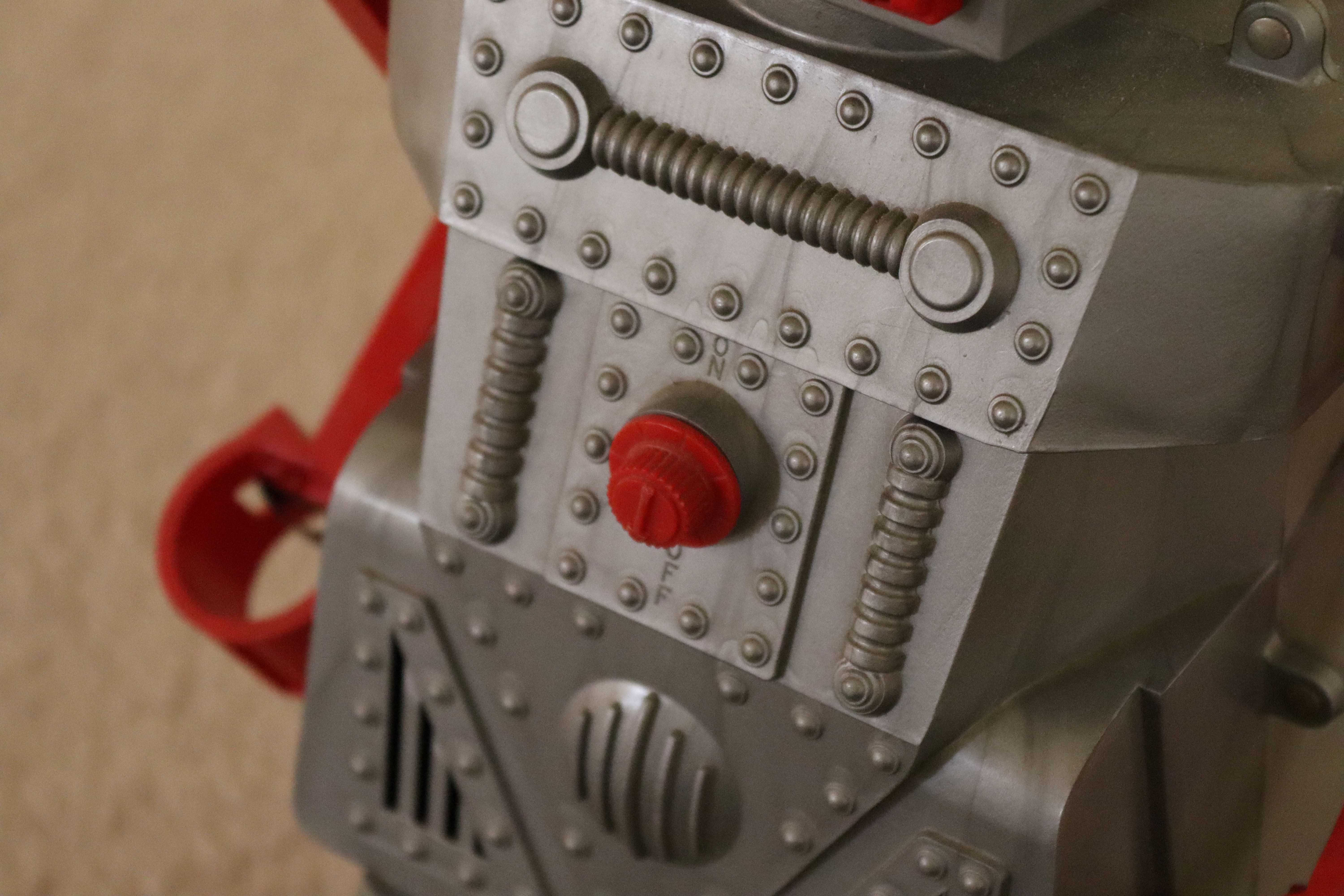
Voice is created by playing a record (hand crank on back). 

Voice is limited to:

"I am Robert Robot, mechanical man.

Drive me and steer me,

Wherever you can.

I am Robert Robot,

Mechanical man."

Why does this matter?  Early "robots" were remote controlled by mechanical cables. Later, electric motors (controlled by wire and switches) replaced the mechanical cables. This was followed by wireless (radio) remote control. Next came internet control (really just long distance wireless). Now, add a camera, microphone and speaker--just "Robert the Robot" for today.

In 1999, I acquired an Aibo, robot dog.

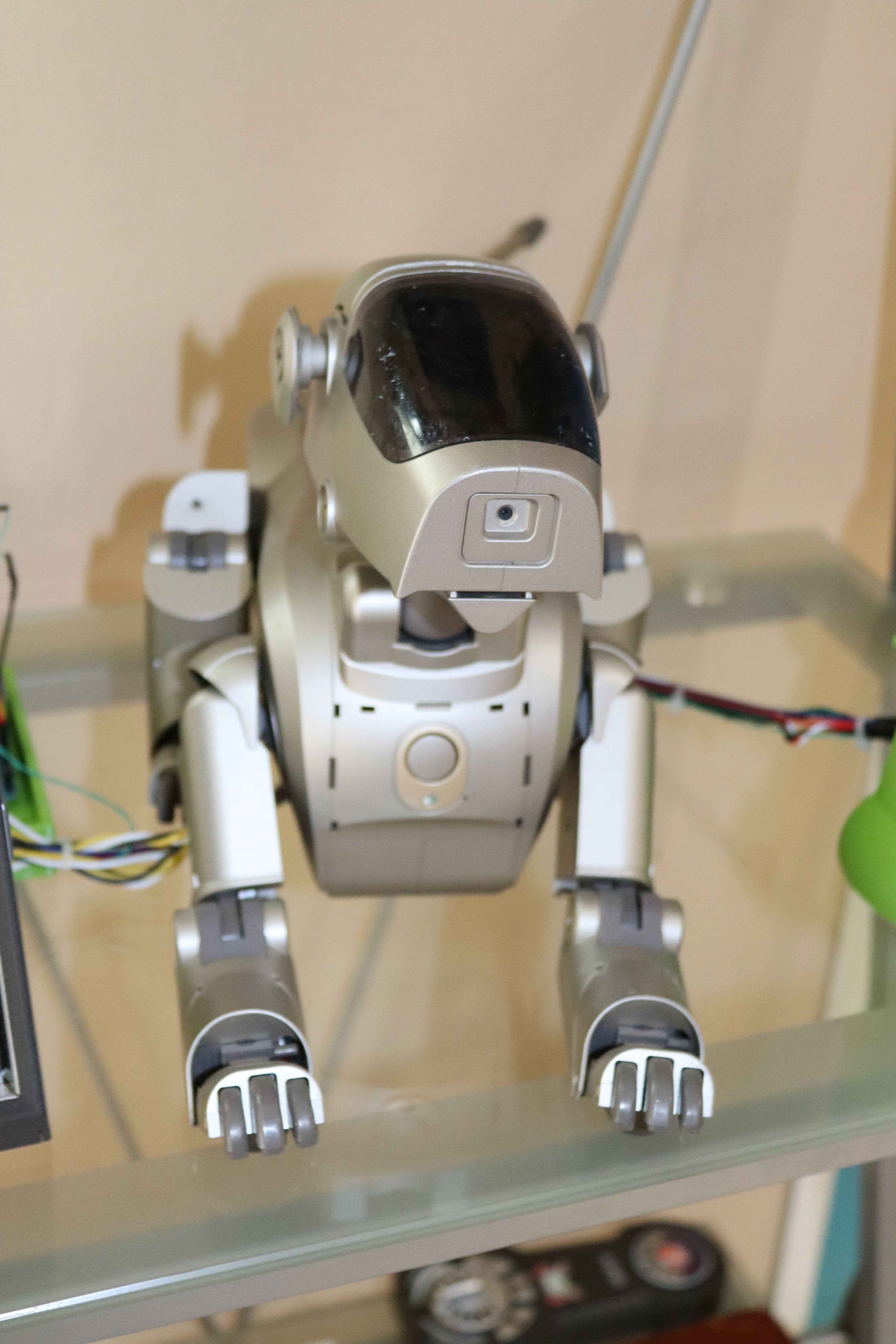
This was declared to be "an entertainment robot."  That's what it did and that was enough. Aibo started "life" as a puppy (could barely stand) and "developed" over time. Aibo learned and reacted to his surroundings (mainly by petting for encouragement, head taps for discouragement). We had a French film crew at our house to tape our robot and reactions for a production, "Robots, Man's Best Friends?"  They had been to Japan (talked to the Sony VP in charge of Aibo) and had taped a Japanese couple with their Aibo. The interviewer was shocked and a bit scared by what she saw. Our Aibo (brought up in a house with my wife and two daughters) was very "friendly," wagging its tail and approaching everyone for interaction.  Our Aibo loved to chase the pink ball and kick it given any opportunity. The Japanese Aibo (raised by a hard working, rarely at home couple) was aloof, indifferent and hardly interested in the ball.  The only difference was the way they were "raised."

Aibo was quite expensive and mechanically complex. Servo motors in some joints eventually developed "the shakes." Potentiometers in servo motors wear out and the feedback loop can't handle this. Aibo's special servo motors are not available. The lithium batteries (I have three) don't hold a charge and they are unavailable (special design).  My Aibo is now an expensive toy that can't leave the charger (no battery) and shakes its head wildly (servo motor problem) on the charger. 

Cozmo is a desktop robot (discontinued).

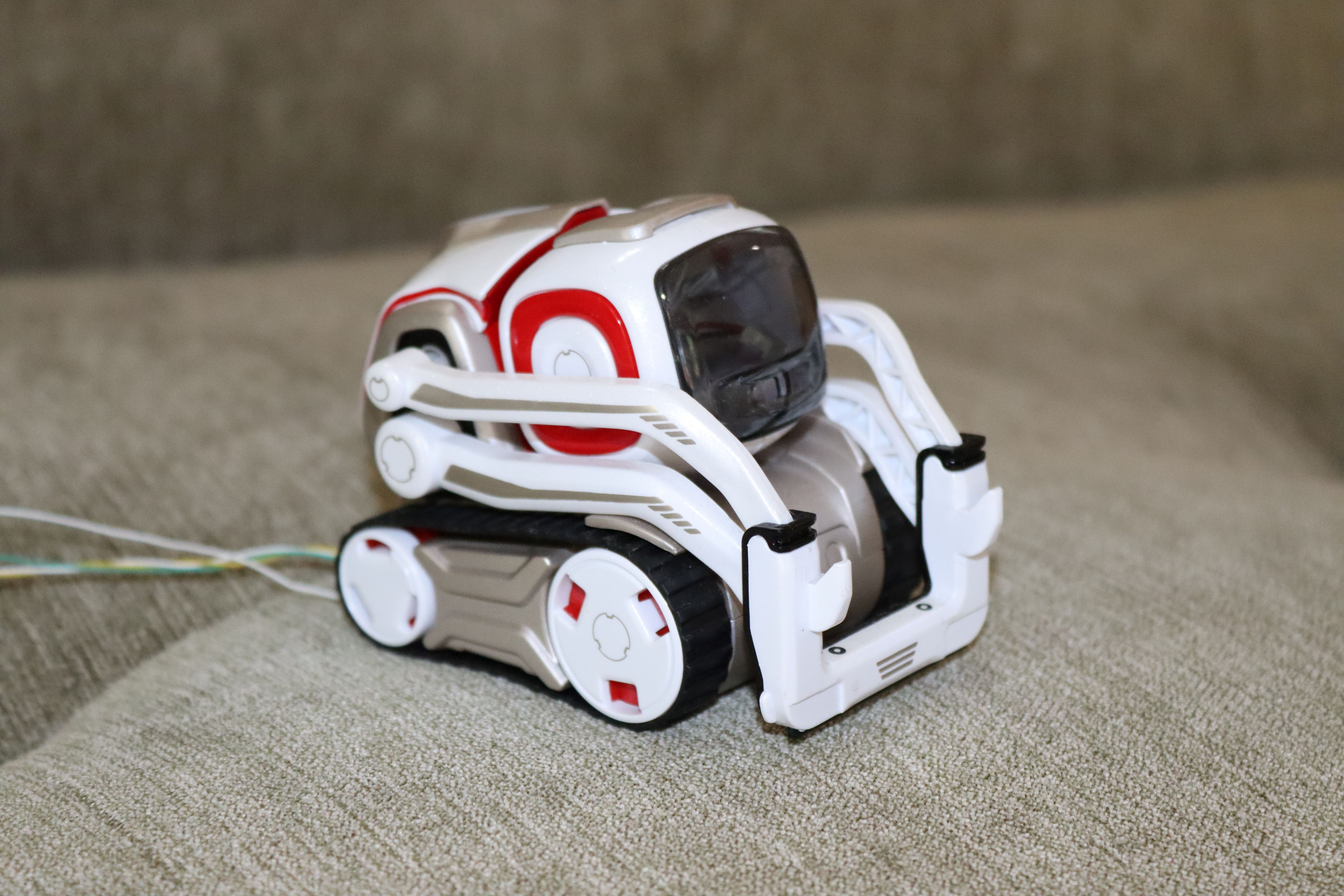
This little character could recognize faces and navigate around specialized cubes. The battery (not user replaceable) failed and that ended its usefulness for me.

Loona (it can be ordered but is not immediately available) navigates independently and can respond to certain gestures and voice commands.

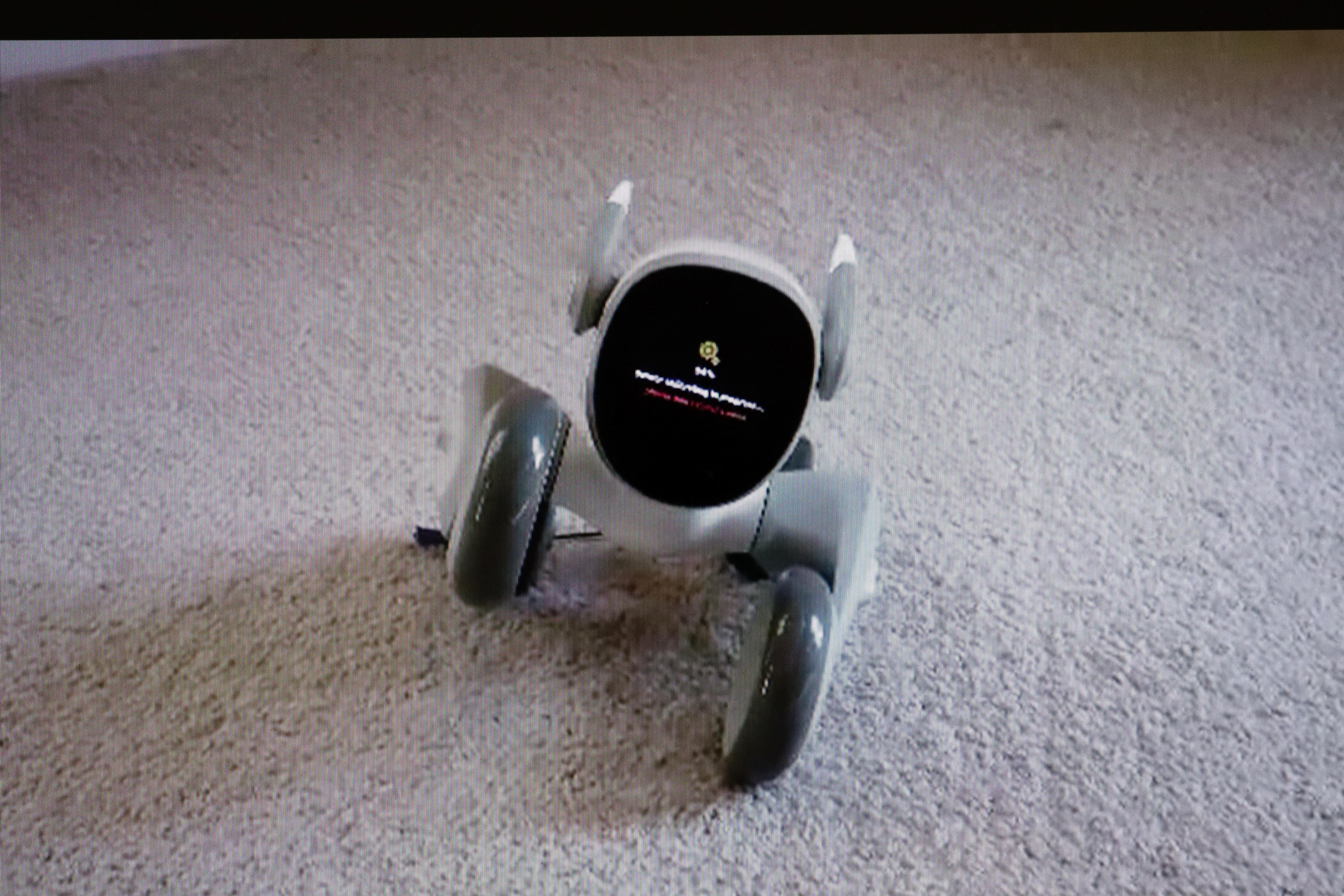
Loona may be able to recharge itself (the charging dock has not shipped).  Loona does not have a user replaceable battery. After about 30 hours of use, my Loona developed a loud "screeching" sound and had to be returned for repair. 

Enabot's EBO X (on Kickstarter, soon to be more generally available) is another of the "run around, charge itself, recognize people, interact remotely" class of robots.

I must mention Astro, Amazon's home robot. Astro is largely an entertainment/social bot--but it can manipulate real world things. It has a load bay, capable of carrying about 2 kg. A "treat dispenser" for pets is also available. Astro is capable of finding people, finding the charger and going to trained locations. 

I have created three "accessories" for Astro. My accessories...

Read more »

ino - 4.15 kB - 04/24/2023 at 16:36

Download

ino - 1.93 kB - 04/24/2023 at 16:35

Download

ino - 1.75 kB - 04/22/2023 at 17:36

Download

Standard Tesselated Geometry - 49.11 kB - 04/22/2023 at 00:36

Download

f3d - 87.63 kB - 04/22/2023 at 00:35

Download

View all 23 files

View all 14 components

  • Ozzy Speaks

    Mike Rigsby04/24/2023 at 16:23 0 comments

    In this section, Ozzy gets a voice.

    This required adding a speaker and speaker power (five volts) according to the schematic below.

    This required a connection from pin 32 of the Arduino Mega to pin 4 of the voice control module.

    "Ozzyvoice0424" was modified to accept voice output statements, while "homely master0424" was modified to send the "detected human target" information to the voice module.

  • Ozzy Comes on Command

    Mike Rigsby04/22/2023 at 00:28 0 comments

    Now, Ozzy will come to me when I say, "Ozzy, come here." I used an 8 x 8 thermal sensor and (another) Arduino Uno to accomplish this. After adding a "Come here" command to the voice recognition circuit, the output of the "thermal sensor Arduino system" can be used to drive the motors forward, right or left. When Ozzy gets near the target (as determined by an ultrasonic sensor), Ozzy turns around and waits for instructions.

    Here is the thermal sensor, mounted to the plywood using 3mm screws.

    Above this is the ultrasonic sensor.

    Wiring for the sensor assembly looks like this.

    Changes to the Arduino Mega (master control) look like this.

    Overall, the top of the bot is getting messy and will probably have to be cleaned up at some point.

  • Voice Recognition

    Mike Rigsby04/20/2023 at 19:35 0 comments

    In this log, I added voice recognition and named my robot "Ozzy." For speaker independent, standalone, cloudless private recognition, an Audeme MOVI (tm) Arduino shield does the job.

    I can select the "wake up" word--I chose "Ozzy." Check out the Arduino code "Ozzy" for my example. The shield is also capable of producing speech; maybe I'll add that later. I connected this Arduino and shield to the master controller (Arduino Mega).

    Wiring connections are made according to this schematic.

    The MOVI (tm) shield must be powered by 7 volts to 16 volts on the Vin pin. It's pretty straightforward, but best to read the manual before starting.

  • Control From the Upper Deck

    Mike Rigsby04/19/2023 at 21:09 0 comments

    Now the movement instructions come from the upper deck--an Arduino Mega.

    It was necessary to rewrite the software for the motor controller (stepper control test.ino) and add control lines as well as set up the Arduino Mega on the upper deck.

    Movement control information can now be written to the upper deck Arduino--which will send control signals to the lower deck.

    The current program (homely master.ino) merely goes forward, turns around, returns and turns around.

  • Second Layer, Sensor, Smarts, Arm

    Mike Rigsby04/18/2023 at 23:26 0 comments

    The lower board is for power, motors and motor control. I am building a second level to manage sensors and worldly interface.

    I'm starting with another piece of 1/2" plywood with four 3d printed supports.

    This will sit on the base unit and look something like this.

    I drilled a 1 1/4" diameter hole in the upper platform to allow my one inch cable connectors to pass through.

    Looking at my base, I noticed that the Arduino's usb port is in a bad position if I ever want to change the motor software. I don't want to disassemble the entire bot every time I decide to make a change (that will surely occur more often than I naively plan).

    I moved the Arduino and the breadboard so that I could reach them without taking the entire robot apart.

    I added terminal connectors and (2) 3 pin connectors.

    Securing top layer to the base with 3mm screws (20 mm length), I am now ready to start work on sensors and the first bit of control.

  • Wiring

    Mike Rigsby04/13/2023 at 21:39 0 comments

    To put this together, I have a schematic drawing.

    The Arduino sketch (which just makes the machine go forward, reverse, left, right, repeat) is provided in the files.

    Here is a photo of the dip switches on the stepper controller. It's set for 6400 steps per revolution (I know, that's crazy--but it's smoother and less noisy) at maximum current of 2.8 amps (maximum according to the motor spec). Each motor only draws about 1.5 amps with a 12 volt supply--so I'm just dipping my toes in the world of stepper motors as far as understanding what's happening.

  • First Adjustment

    Mike Rigsby04/13/2023 at 16:46 0 comments

    For the first test, the component configuration looked like this:

    This works, but the 4.5 pound battery (over the caster wheel) creates a weight imbalance such that the front wheels tend to slip when making turns.

    The solution is to move the battery closer to the drive wheels. This is actually consistent with Astro robot, where most of the weight is in the front with very little toward the cargo bay/caster wheel.

    Sometimes it is easier to "see mistakes in action" rather than "planning for all possible faults in advance."

  • Base Construction

    Mike Rigsby04/13/2023 at 13:23 0 comments

    So many choices--which wheels to actually use?

    What size should the robot be? The Heathkit Hero robots (sold in the 1980's--I never had one of these) were 20 to 40 pounds; 40 pounds for the one with an arm. Astro, which can carry some load, weighs 20 pounds.

    I cut an 18" square piece of 1/2" thick plywood for the floor. I used a quart size paint can for a template to round the corners.

    Next, I cut slots to allow a bit of room for wheels.

    I 3d printed a wheel connector/shaft and secured it to the wheel using 3mm screws.

    I attached an 8 mm to 6.35 mm shaft coupler (8 mm end) to the 3d printed shaft.

    I bolted NEMA 23 brackets to the base.

    Next, I mounted a motor and wheel.

    This was followed by the second wheel.

    Next, I drilled a 1/2" hole through the plywood and inserted the motor wires.

    Next, I added a 1" caster wheel to a 3d printed extender, then attached this to the rear of the platform.

    I added a 5 amp fuse and battery connectors to a toggle switch (on/off).

    I mounted the 3d printed switch holder to the platform.

    Next, I installed the switch.

    This was followed by attaching the Arduino and driver boards to the plywood using Velcro. The battery was secured using 3d printed corners.

    Control of the stepper motors is done through stepper motor drivers (less than ten dollars each).

    These drivers require 12 volt power. The four stepper motor wires are connected to the A and B terminals. Positive 5 volts (from the Arduino) is connected to the plus terminals of the "signal" input. Note that this does not use ground as common.

    The Arduino must provide a pulse (this controls the motor speed--shorter the pulse, faster the speed). The Arduino must also supply a high or low signal for motor direction. Last, but not absolutely required, is the enable signal. If you do nothing, the stepper motor will draw current and stay "locked" in the position where it last received a pulse. If enable is activated, the motor will not draw current and will freely turn.

View all 8 project logs

Enjoy this project?

Share

Discussions

Peabody1929 wrote 04/24/2023 at 17:33 point

"Ozzy, bring me a cold one."

  Are you sure? yes | no

Mike Rigsby wrote 04/24/2023 at 18:33 point

It's not out of the question--I did something similar with Astro "https://www.instructables.com/Cool-Can-on-Command/".

When Ozzy has an arm and is able to go (on command) to specific places, it might happen.

  Are you sure? yes | no

Similar Projects

Does this project spark your interest?

Become a member to follow this project and never miss any updates