 Jarrett Cigainero
One of the goals of this project was to build the circuits out of as much junk as I could find with the exception of a few slightly more specialized parts such as the deflection amp's output stage; NOT including the flyback transformer.
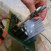
The flyback transformer is made from a 3D printed spool I designed and then 3D printed on a friend's resin machine. I then used ABS to 3D print the casing. The spool design includes a drill chuck attachment to making winding the 1600 HV windings easier. The HV windings MUST be well insulated from each other every 40-50 winds or they will arc over and burn out your transformer. I used RTV and kepton tape for this.
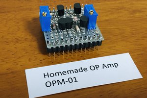
All circuits, except the Raspi and it's DACs (well, technically they have their own), are using Op-Amps for amplification, detection, and PWM generation for the power supplies. Schematics here: https://github.com/RingingResonance/ADSB_Sweeper/blob/master/Collection/Collection.pdf Of note: The mosfet driver transistors can be replaced with IXDN602 duel low-side mosfet drivers or equivalents with the inputs to the comparator Op-Amps swapped so that the comparator outputs are inverted.
Just after the pre-amp stage, I have a circuit that monitors signal input and deflection power supply integrity. This circuit cuts the beam if one or both supply voltages fails, or there is no signal input so that the CRT's beam isn't in one spot the whole time burning a hole in the phosphors. This circuit has saved my tube countless times already! It also acts as an indicator for signal input when the intensity is low.
Another goal of this project was to have everything powered by a single supply such as 12V. The two power supplies achieve this well, including getting the CRT's heater voltage from one of the tapped windings of the flyback transformer. However, there is a problem with the deflection amp power supply. Since I kinda just threw it together, it can' supply enough current for the deflection amp and I get clipping. That is why I'm currently only using about half the screen area.
Update: I burned up the driver mosfet for the deflection amp power supply and this forced me to repair it using the updated schematic on the github repo that uses a center-tapped 1:2 transformer and two mosfets that alternate using a 7474 flip-flop. This updated design works much better than the original one, and I can now drive the amp at 20V full deflection, though the limiting factor now being my steering coils. They get pretty toasty! I've also update the intensity control circuit to not depend so much on the neon bulb for regulation. To properly adjust; turn beam intensity down until it's just at the cutoff, then turn the regulator pot up until the neon bulb just begins to turn on. If the intensity of the CRT becomes visible again, then adjust brightness until not visible and adjust neon bulb until it just barely turns on. Repeat until neon bulb only turns on when intensity is below cutoff, and neon bulb striking doesn't bring CRT intensity back up to visible level.s
I can't recommend this project to beginners. It involves high voltages that can KILL you. So I left the details of the schematics out for now. I had built the circuits before the schematics anyways and they require some tinkering to get them to work properly.

 Justin Scott
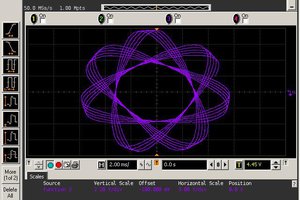
 Mitsuru Yamada
 vybhav-nag
Just got one of these tubes at an estate sale, so I was looking for something I could do with it. I initially thought it was an electrostatic tube, but I guess not!