0%
0%
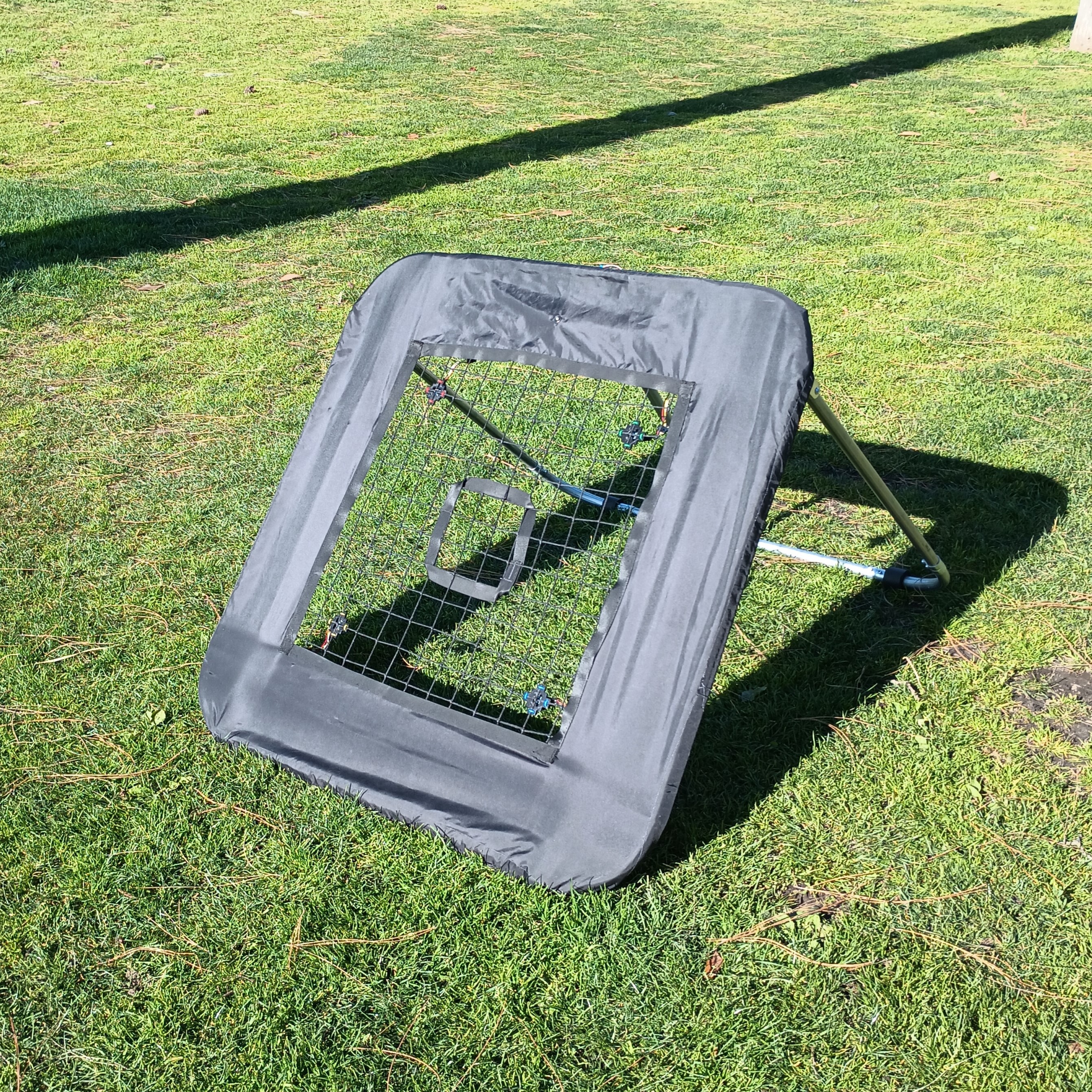
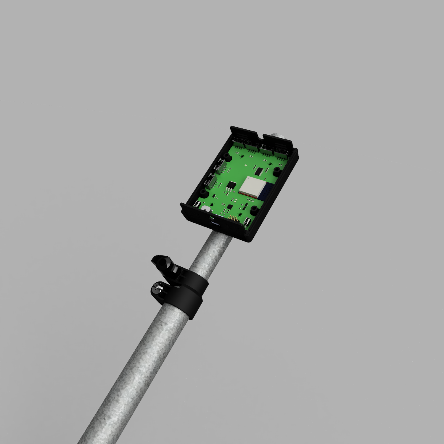
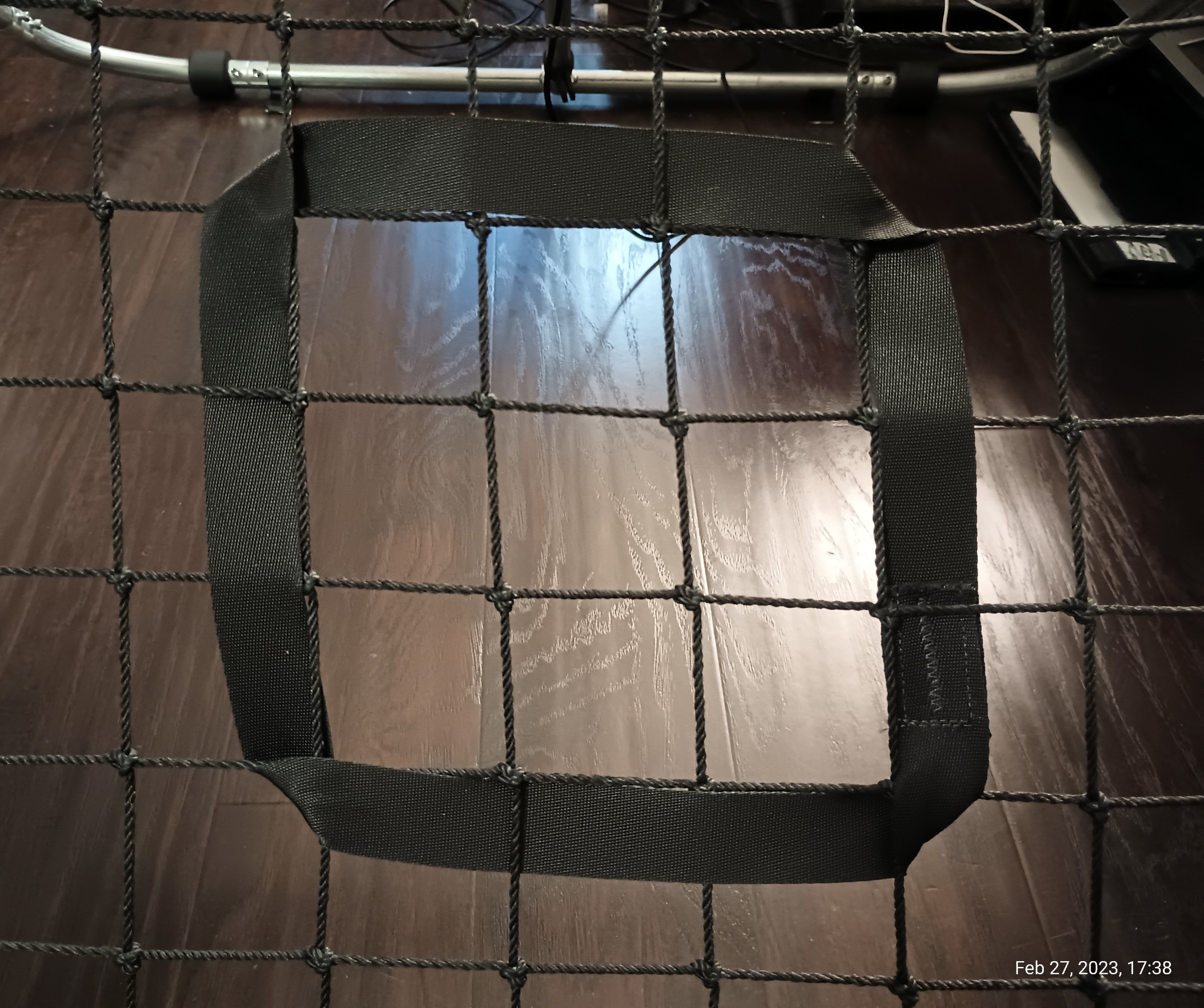
Accuracy-Sensing Smart Sports Rebounder with ESP32
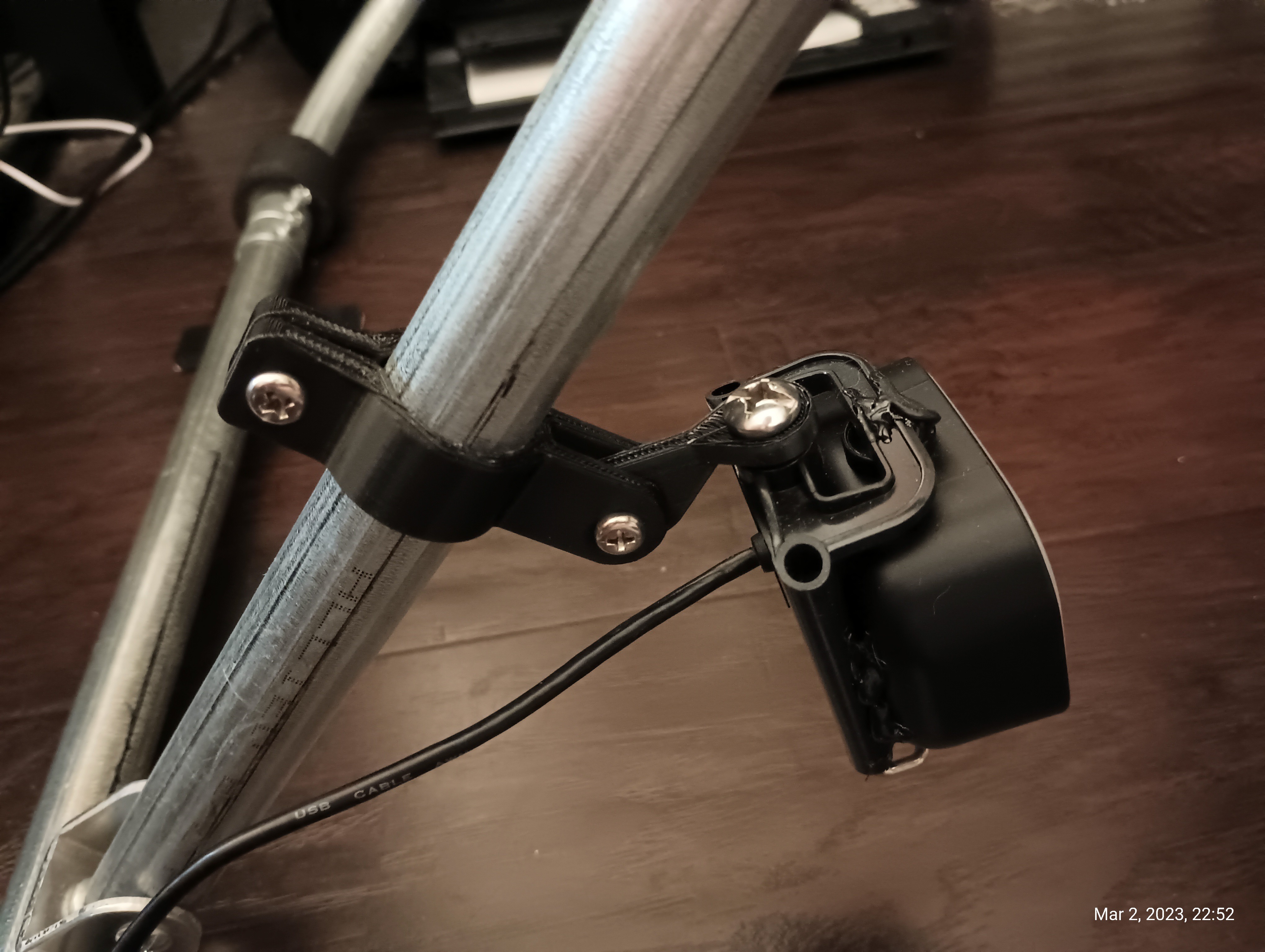
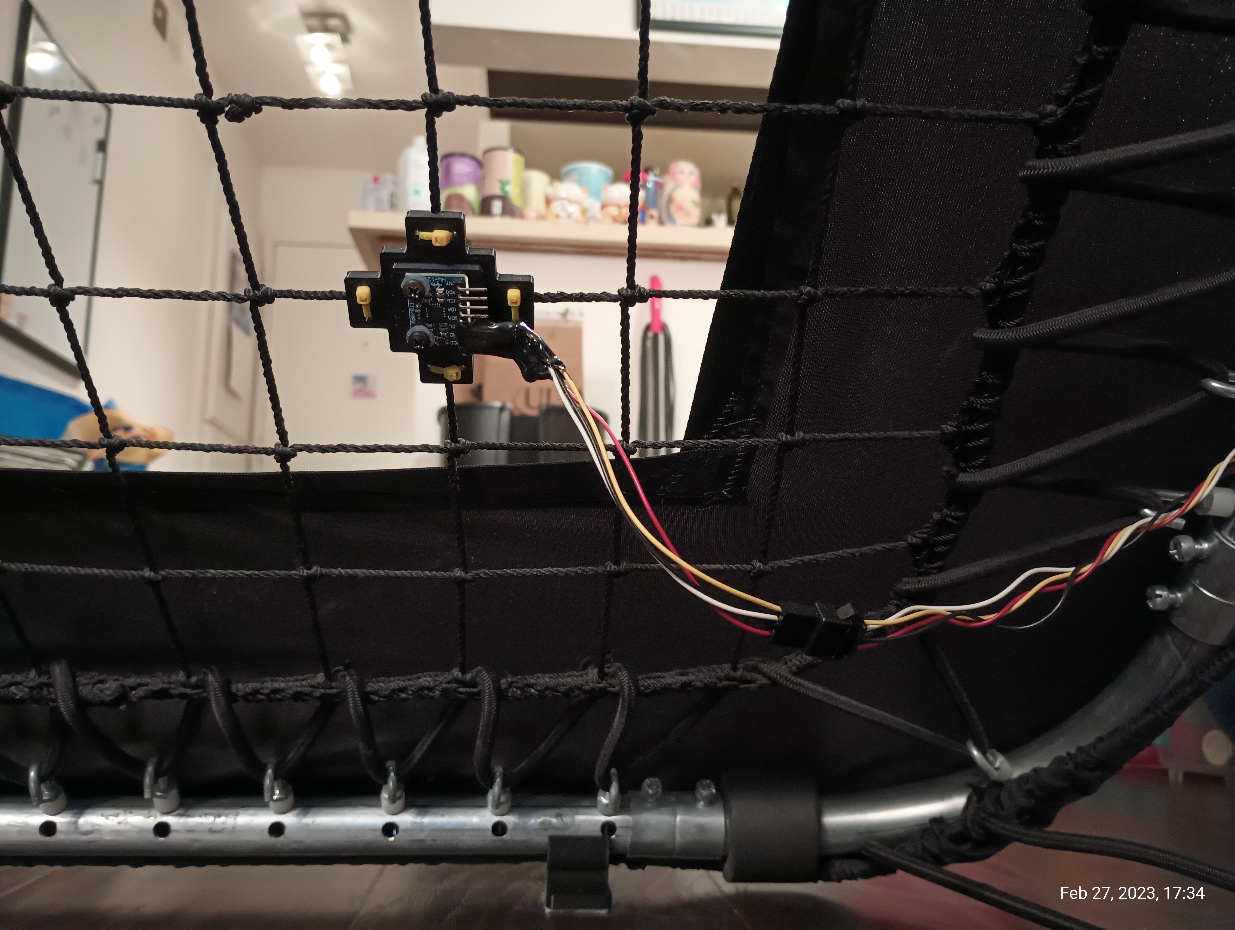
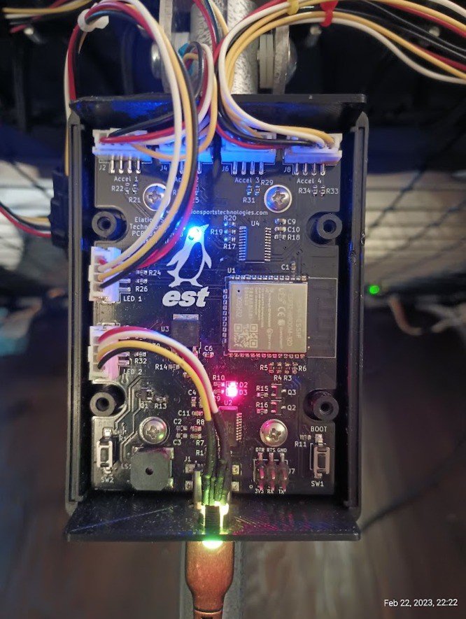
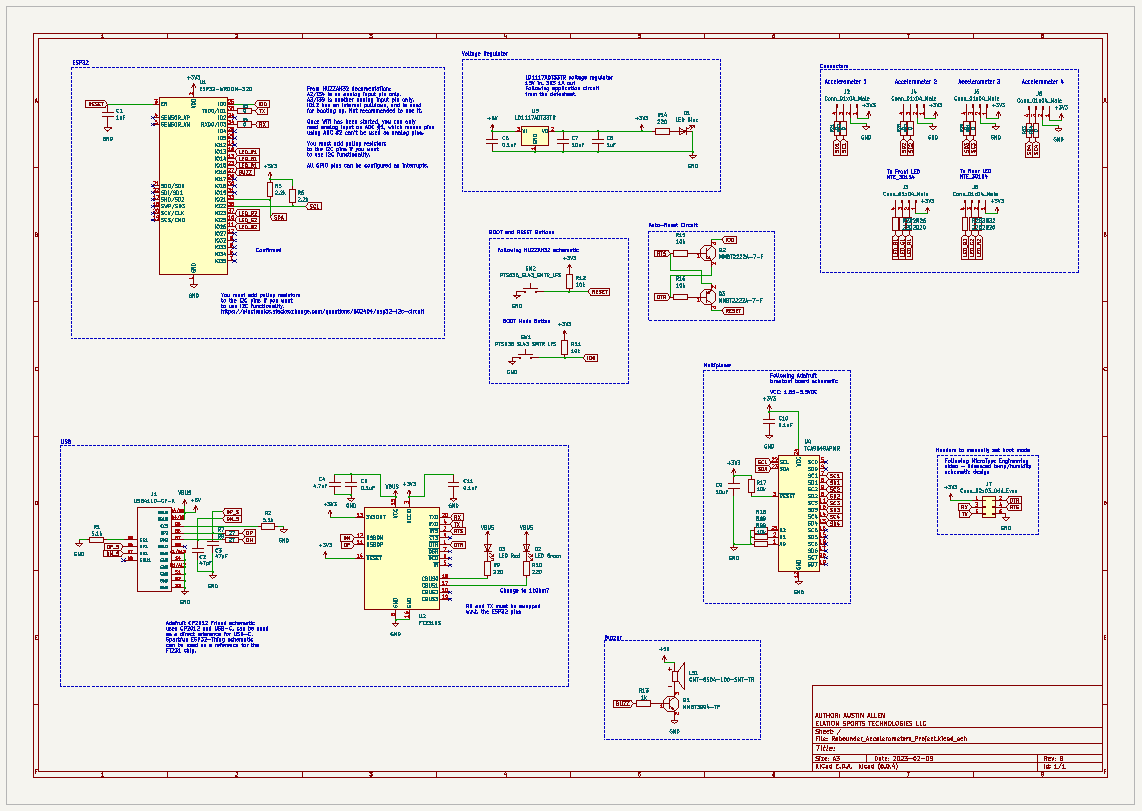
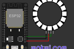
I created a smart sports rebounder using 4 x accelerometers with an ESP32 microcontroller and a neural network to locate soccer ball bounces
 Austin Allen
Become a Hackaday.io member
Already have an account? Log in.
Just one more thing
To make the experience fit your profile, pick a username and tell us what interests you.
Pick an awesome username
hackaday.io/
Your profile's URL: hackaday.io/username. Max 25 alphanumeric characters.
Pick a few interests
Projects that share your interests
People that share your interests


 Gina Collecchia
 Open Technology
 bcwadell
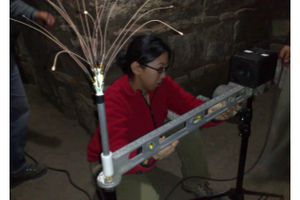
Cool project, utilising different I suppose unconventional techniques and materials.
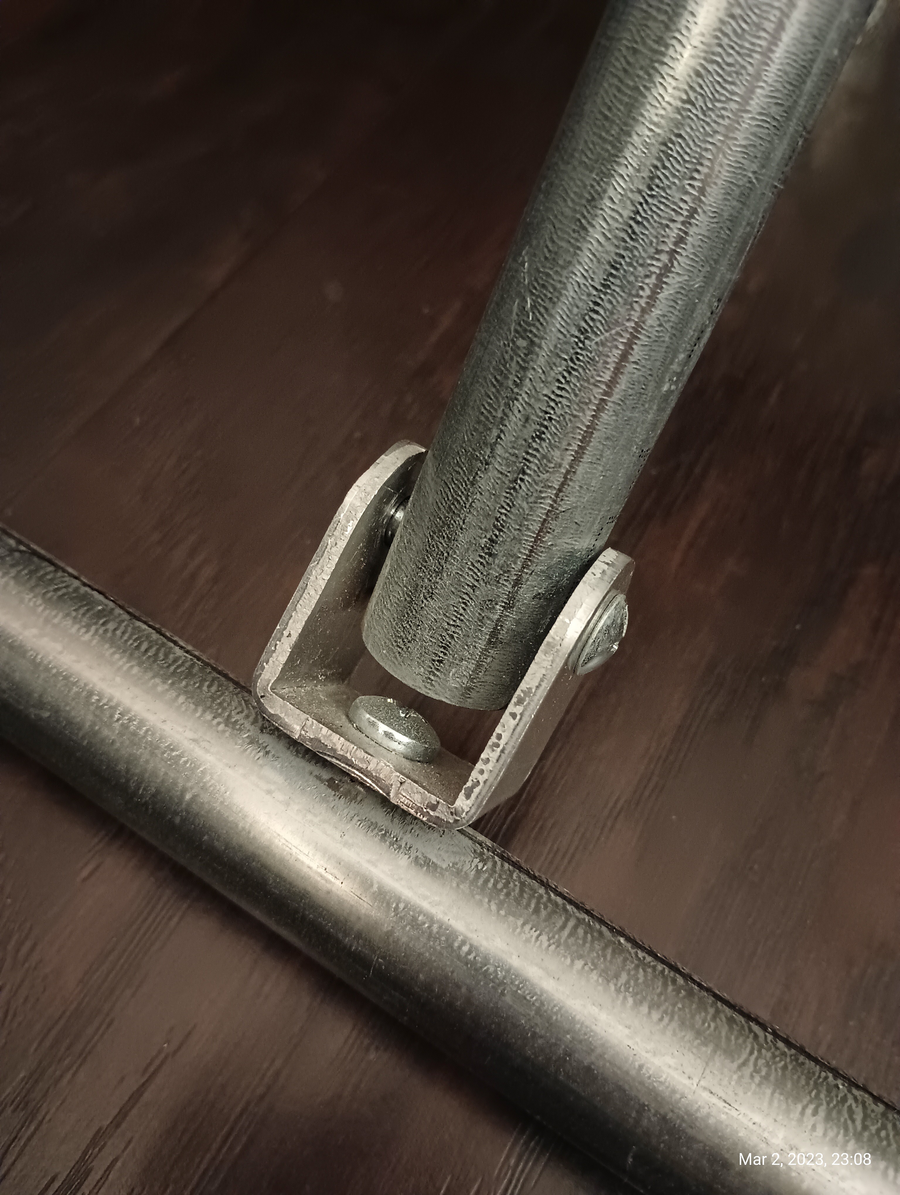
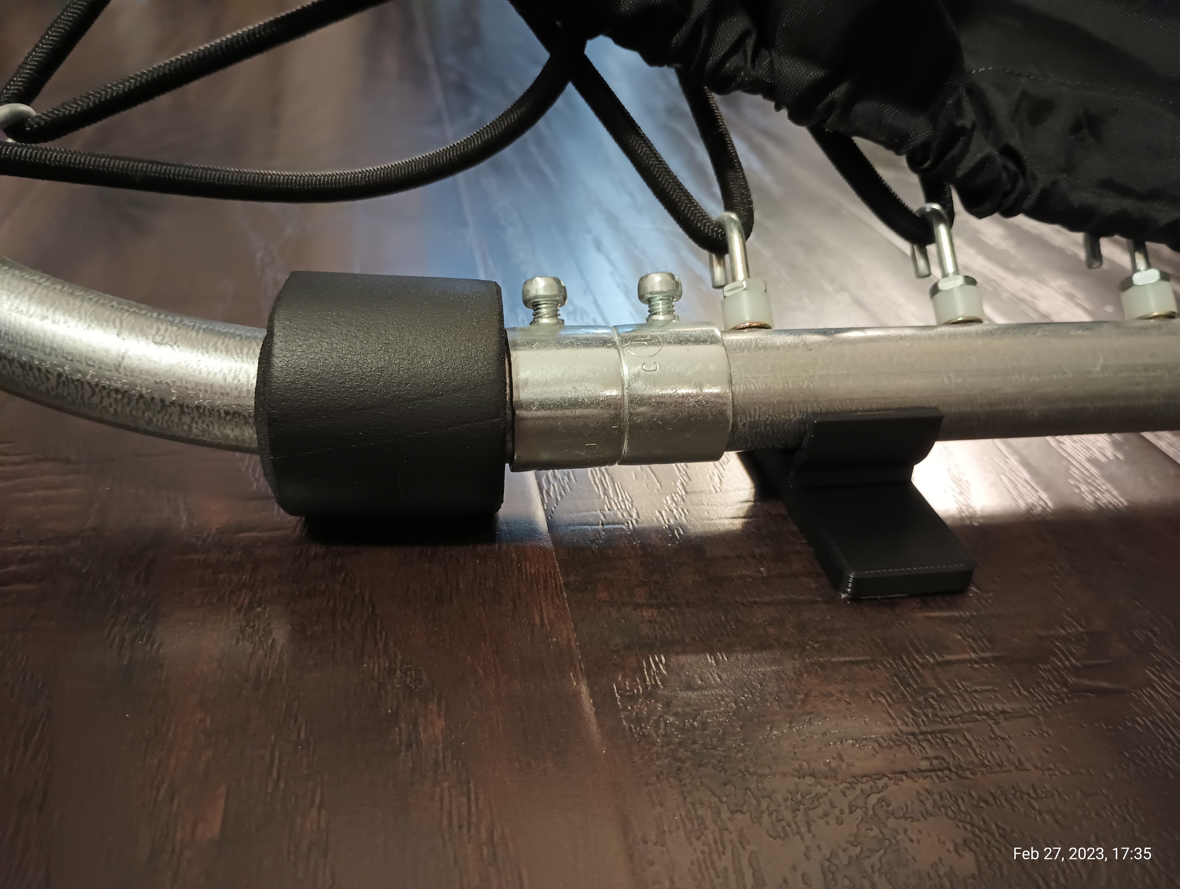
Why utilise EMT without routing the wires through it? You will have to think of waterproofing if in that environment and making sure there are drain holes etc. Plus what way is it treated against corrosion, that’s a point to consider when cutting etc.