 Steph
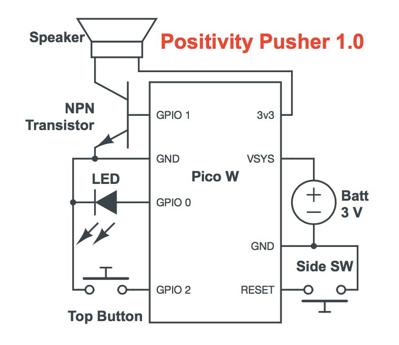
StephThe Positivity Pusher delivers empathetic messages of encouragement at the push of a button.
Hardware:
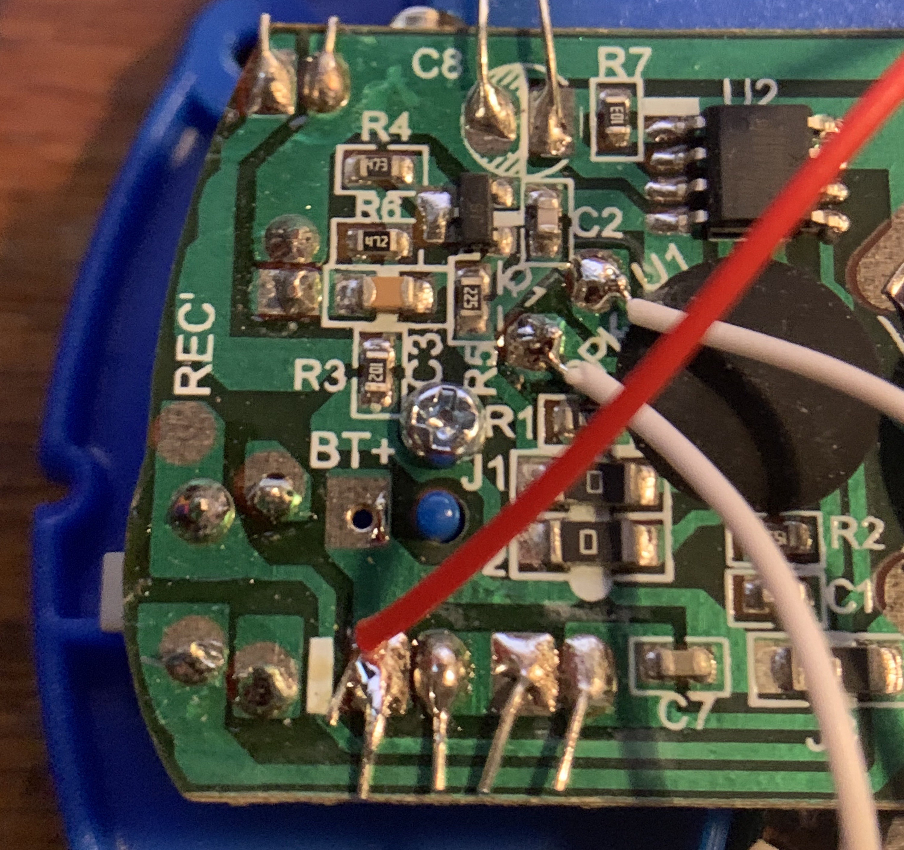
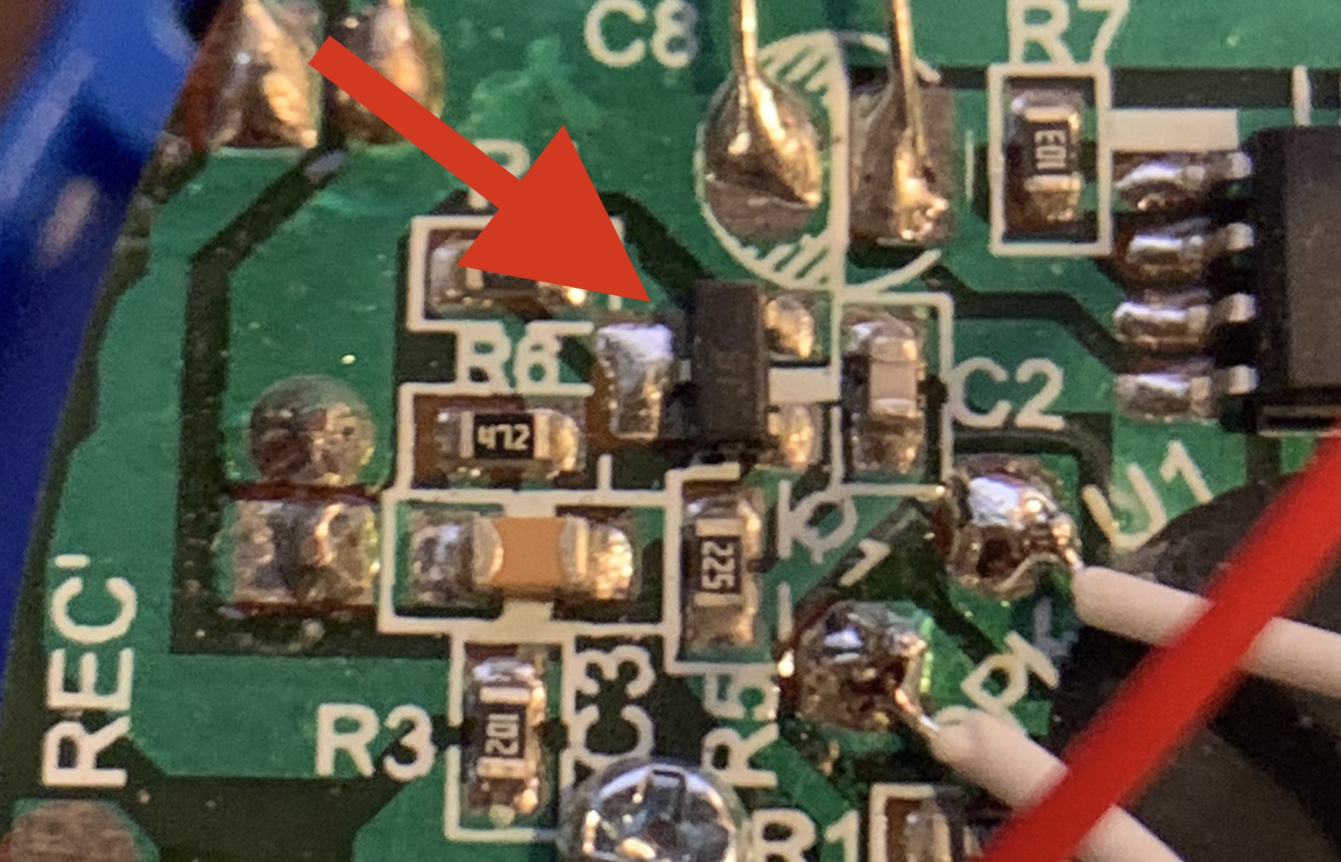
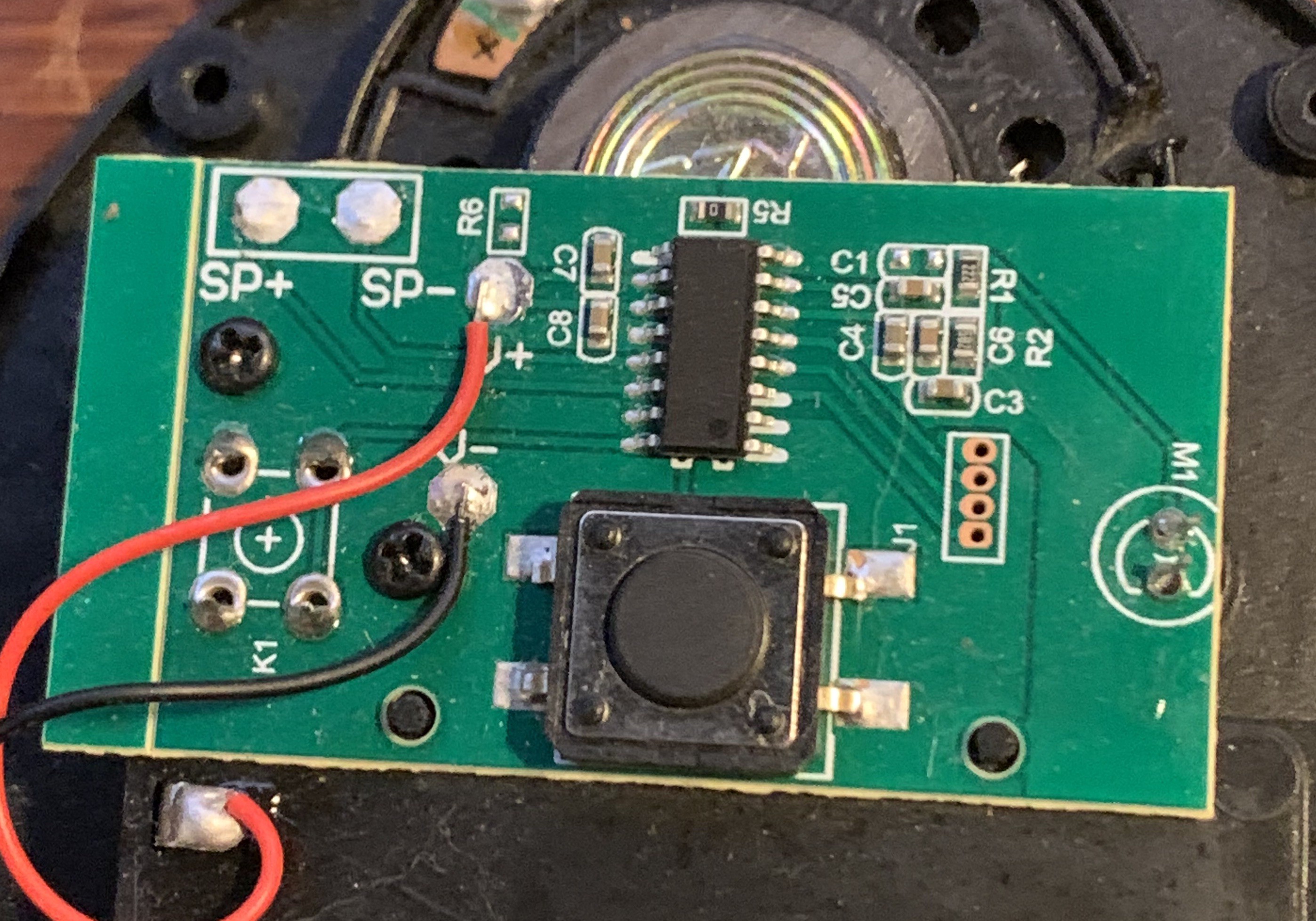
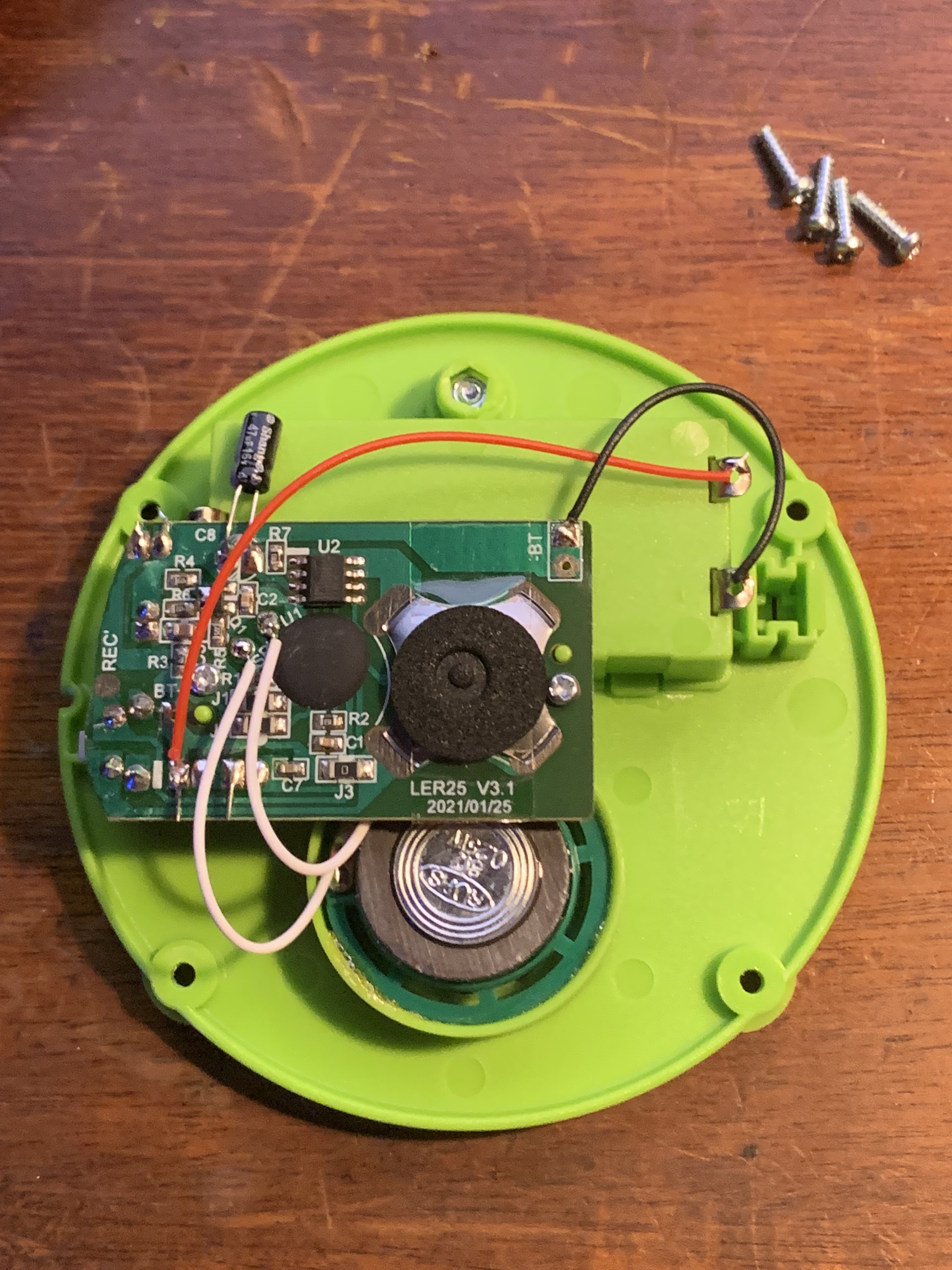
The Positivity Pusher uses an inexpensive Raspberry Pi Pico W ($6 new) housed in a repurposed recordable message button (about $3 used).
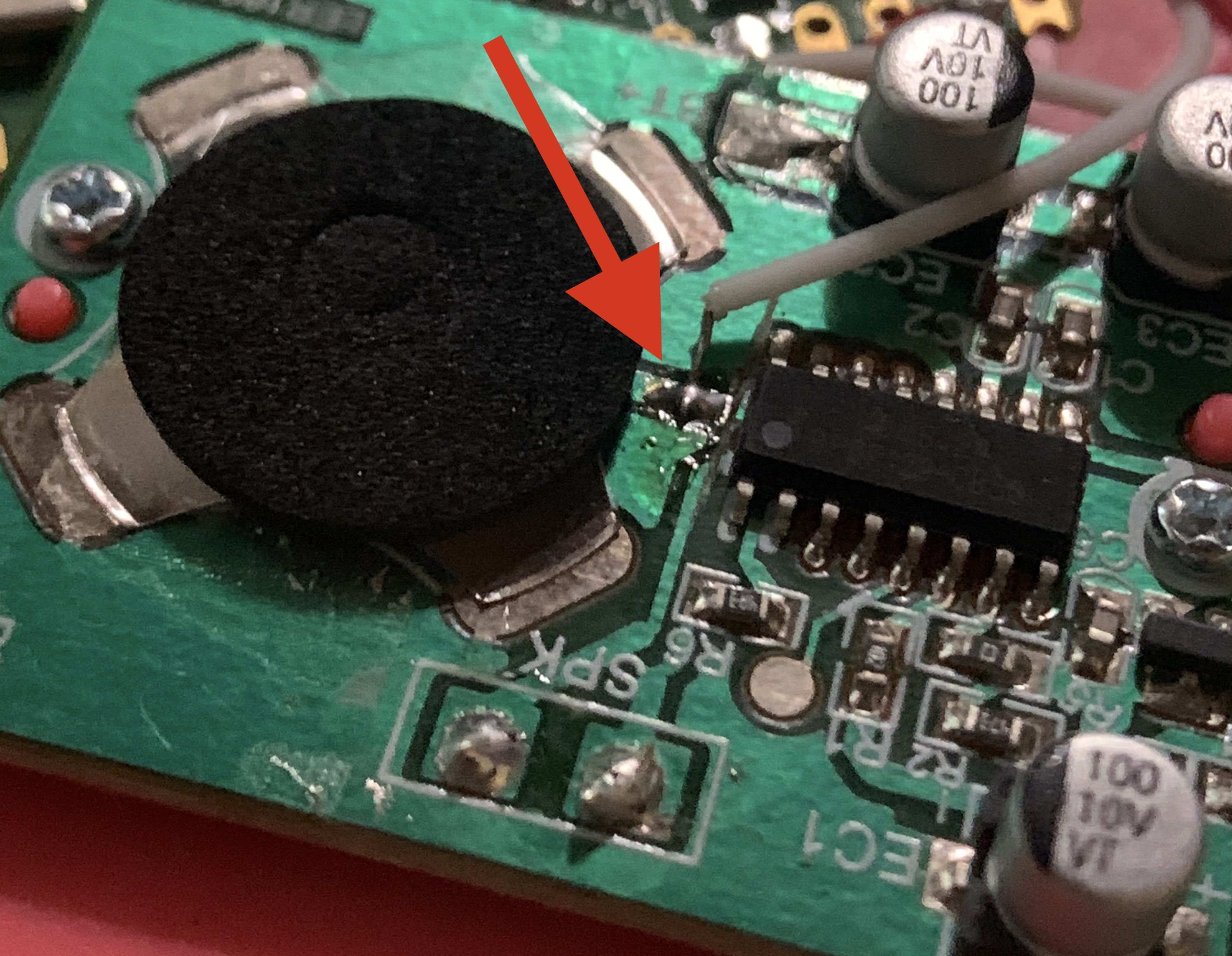
Visual feedback is provided by replacing the mic with an LED. By repurposing existing hardware and adding only the most necessary additional hardware, The Positivity Pusher is designed to be easy for anyone to build, with a total cost of under $10.
Software:
The Pico W runs CircuitPython. The script connects over wifi to external APIs for AI text completion and speech generation, playing back the resulting audio file whenever the button is pressed.
In addition to downloading fresh messages, the code also implements a web-based UI and self-broadcasted access point, where the user can provide their network credentials and customize their message prompt.
Building Your Own:
Here's what you'll need:
- Soldering iron
- Computer with USB for programming the Pico W
- The Parts
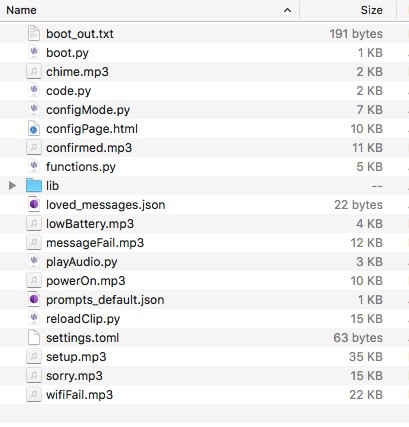
- The Firmware
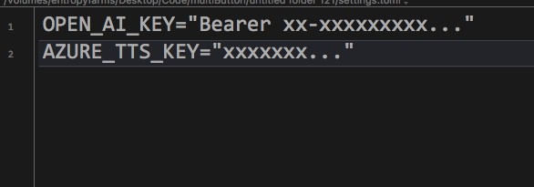
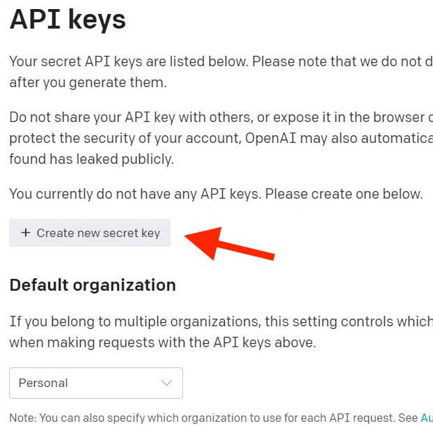
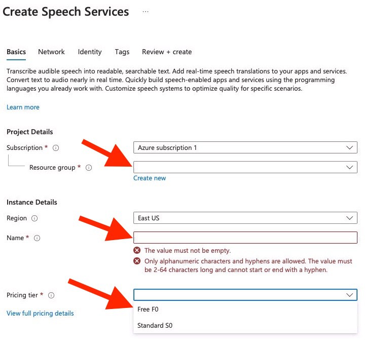
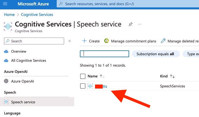
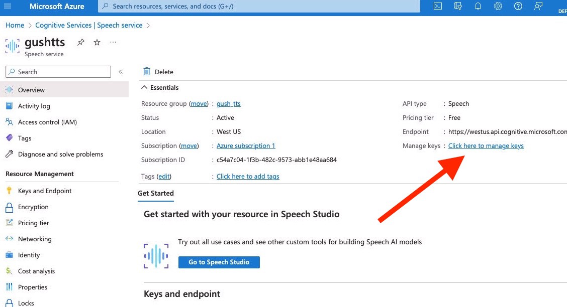
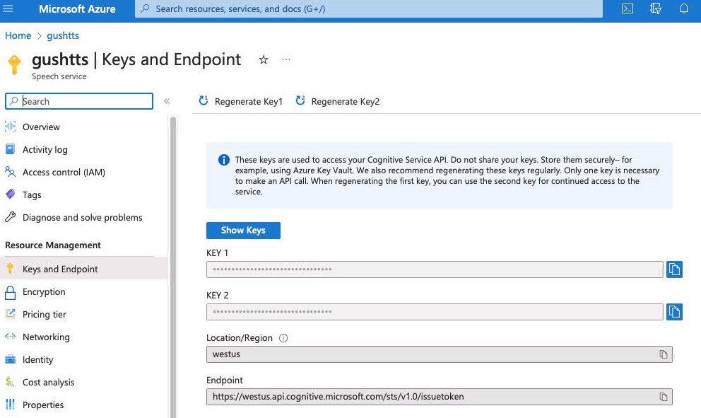
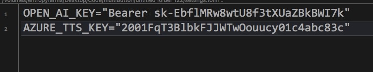
- API keys for OpenAI and Azure Cognitive Speech
Details can be found here:
- Written Build Instructions
- Video coming soon
More Info:
Positivity Pusher is designed to be made with secondhand parts to maximize enjoyment and minimize cost. It also employs a number of hacky solutions and compromises to achieve it's low cost and simplicity. Here are some highlights:
- Run the Pico W for months on just 2 AAA batteries.
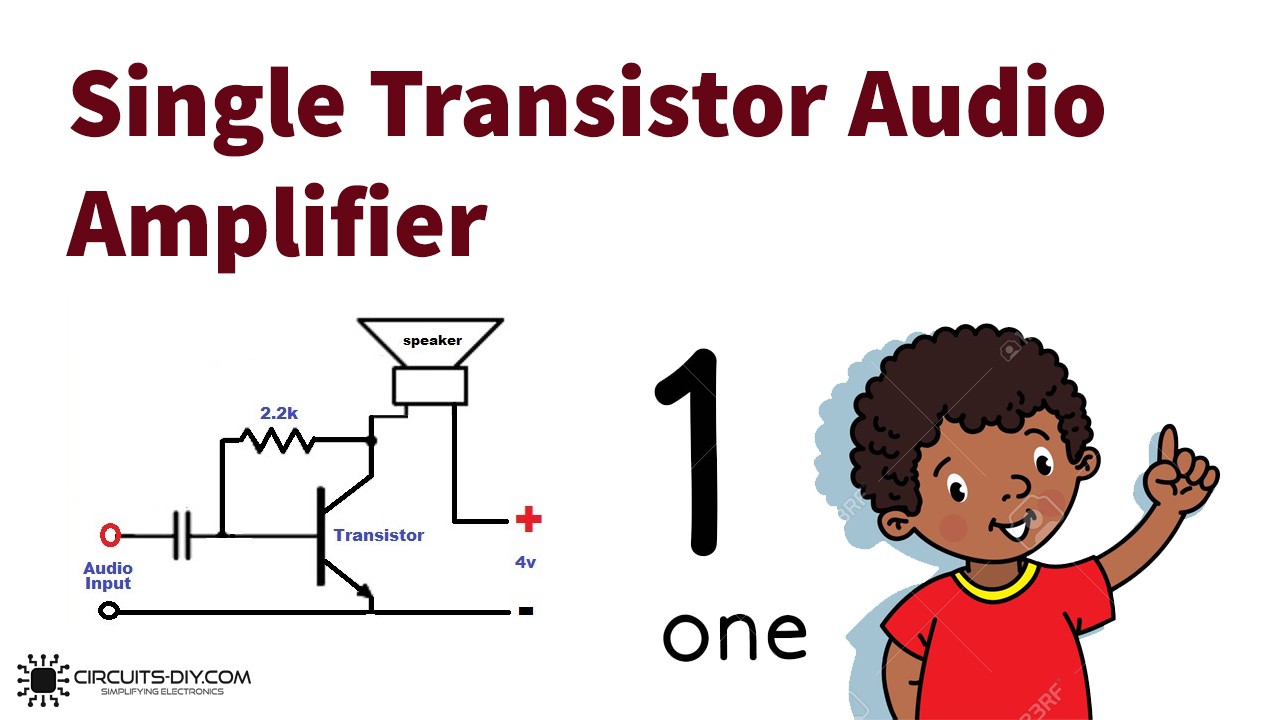
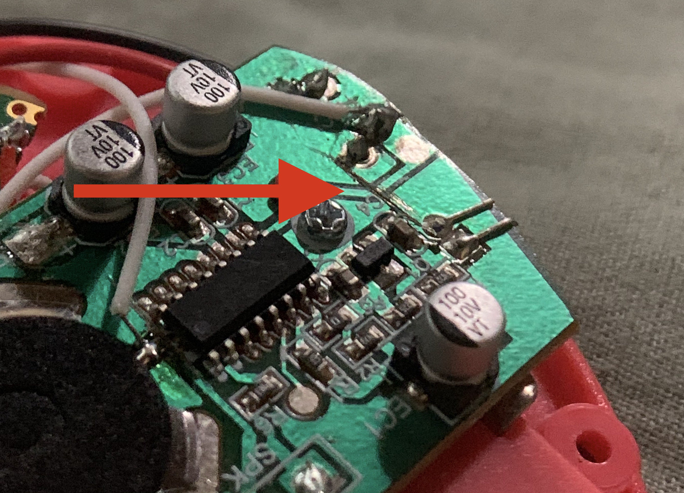
- Single Transistor Audio Amplifier
- CircuitPython Volume Boosting
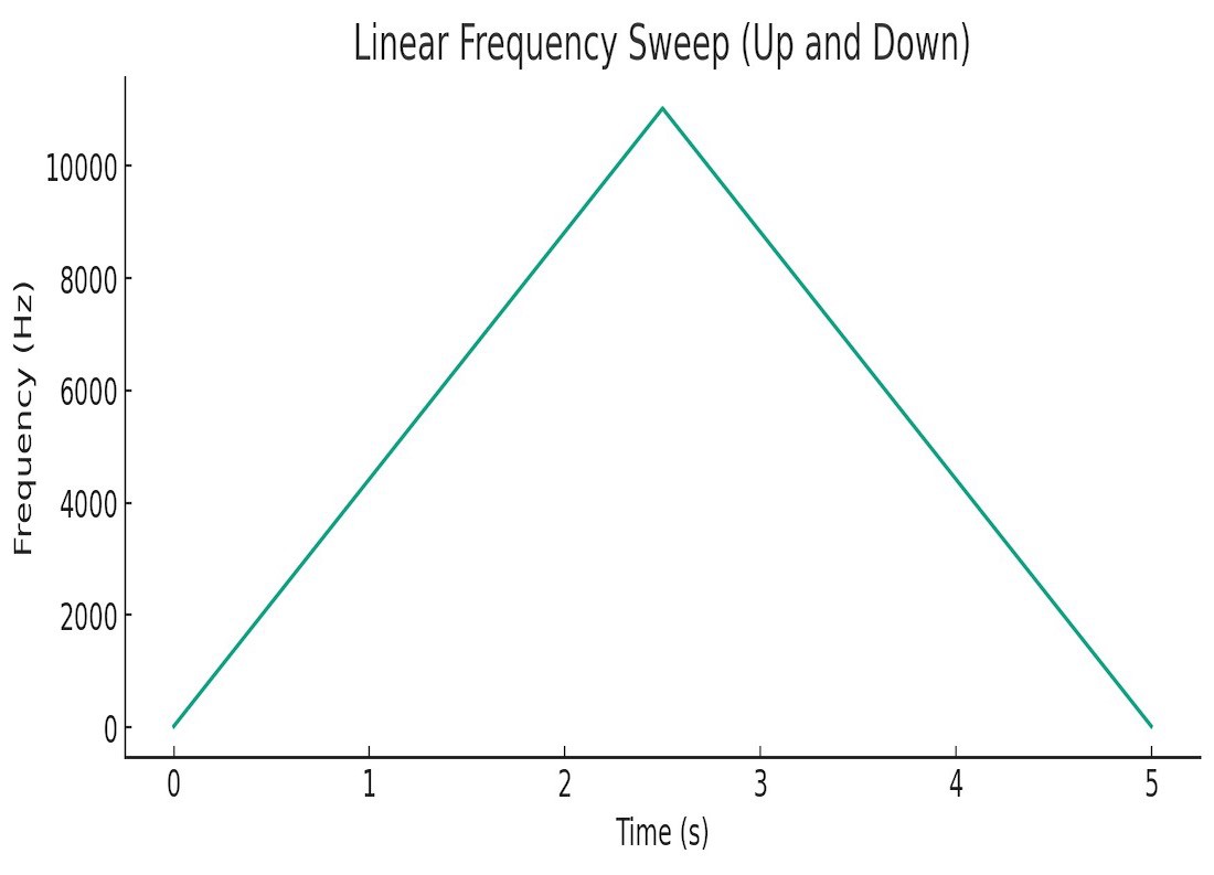
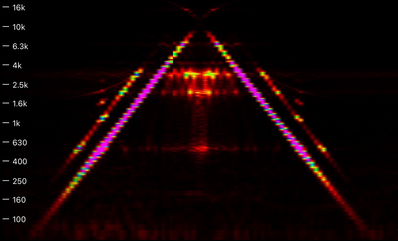
- MP3 Speed Manipulation
This page is a work in progress, please check back as additional details will be added!


 stupid
 Chris Miller
 Saul Cozens
 DeepSOIC
I see where you're coming from about the speaker driver. The source content volume varies a lot. Speech only needs to 300 to 3k limit bandwidth at the transducer. Distortion can be ok double-figures. The minimalist single transistor is virtually class c and normalises the signal. An audio IC amp is a non starter isn't any good with 2.x something volts supply. Can get more power in speaker by a H bridge driver from 2 npn/pnp pairs off two gpio. Complementary signal while active and both drive low when silent. A possibility the gpio(s) could direct drive the transducer minus any transistor(s).