 Steph
StephThe Positivity Pusher uses PWM to generate it's audio output. The GPIO pin produces enough volume to drive small headphones, but to do any serious speaker shaking we'll need to amplify that signal.
In keeping with the project's ethos, I wanted to use a circuit with the most simple possible execution, as well as using salvageable parts. Looking around for simple audio amplifiers, I found many "simple" circuits with dozens of (sometimes exotic) components and complicated theories explaining their operation. Eventually, I zeroed in on this design with one transistor and just two other components. You know the circuit is simple when it comes with clipart of a child:
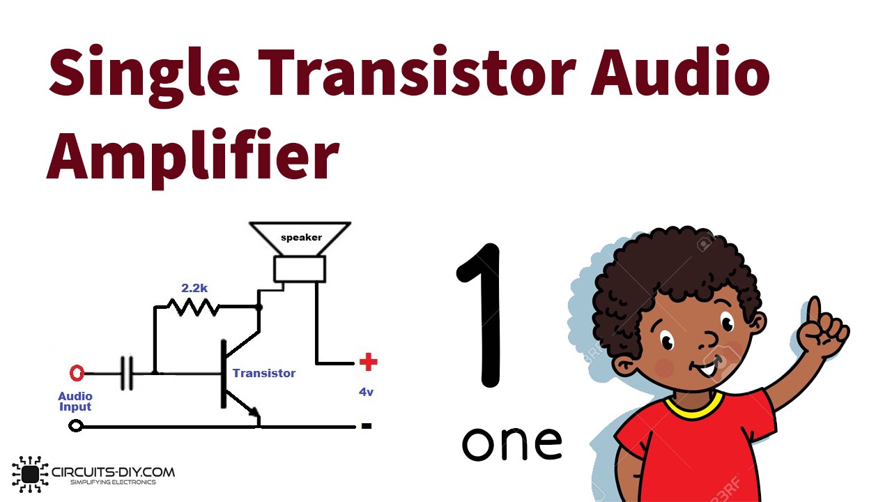
I took this design and further reduced the complexity by a factor of 66%, by just ditching the capacitor and resistor entirely. Streamlining!
In the Positivity Pusher version, as seen in the wiring diagram here, +3.3v is fed directly into the speaker from the Pico's 3v3 pin. It then flows into the collector of the transistor and out of the emitter, to ground. The weak audio signal is modulated onto the transistor base pin, resulting in the amplification of the signal through the speaker.
When I tried to seek advice about my amplifier design, people online told me that it was "not good." Unfazed, I kept inquiring. They told me I should "use a breakout board" or "the famous LM386." I told them I want to keep it simple. That's when they told me that I should "read some textbooks" and I "shouldn't trust random schematics on the internet" and also that my circuit is known as a "Russian Roulette Special."
Well...

Can't Argue with Success
I think my single part amp is pretty neat, and I don't think it's dangerous!* And despite what smart people online would lead you to believe: it works! But it isn't perfect. In fact...
It's Pretty Far From Perfect.
- It drives DC through the speaker.
- It's not efficient. At all.
- The frequency response is not flat. At all.
- Probably other bad stuff I'd know about if I read a textbook.
However, it Has Two Major Benefits!
- Minimalism: You can't reduce the part count any further than this.
- It really works! Opinions aside, the design verifiably boosts an audio signal.
But how bad is it?
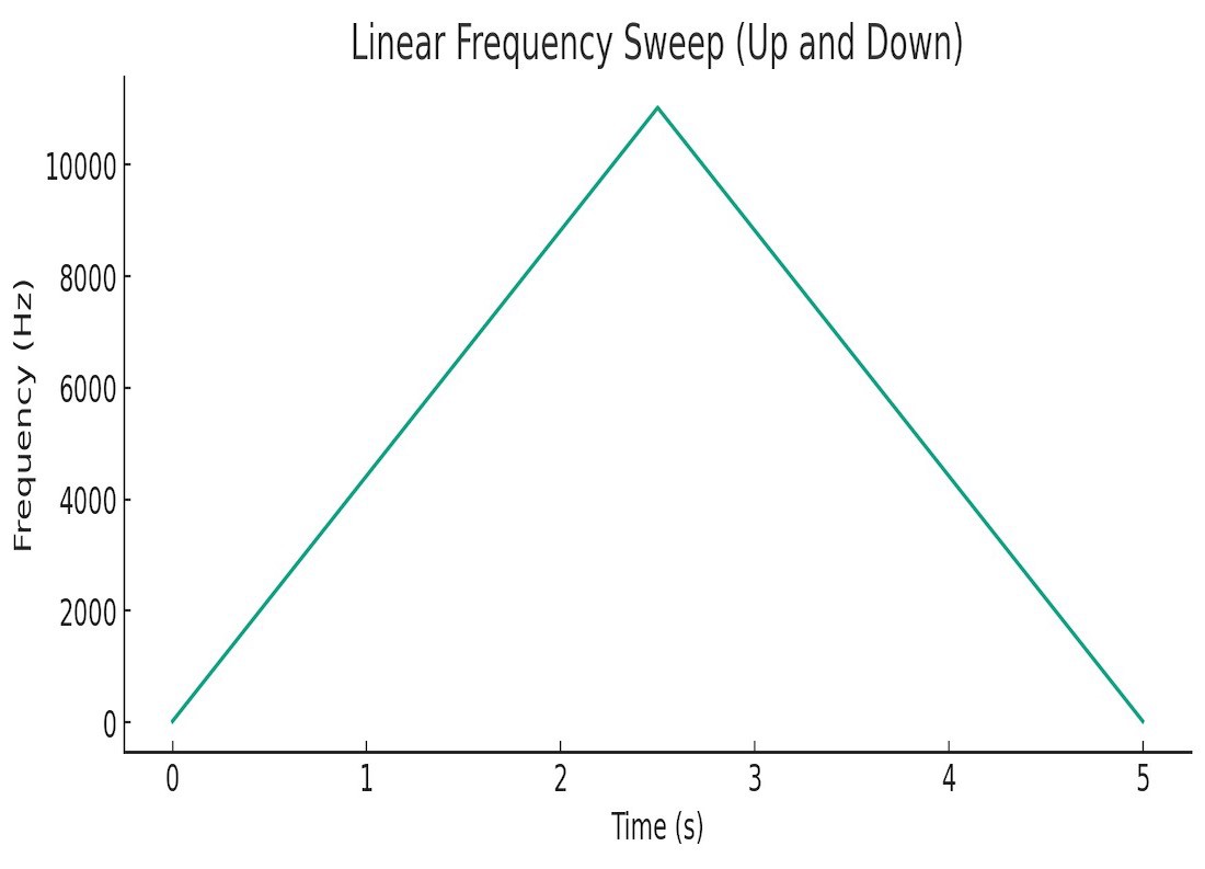
To get a sense of how the amp is performing, I made a test file for playing back through the amp and speaker. This is a 22050hz wav file, so the top frequency it can reproduce is 11khz. Here's a graph of the frequency over time:
And here's a spectrograph of our amp playing that frequency sweep through the speaker in a button.
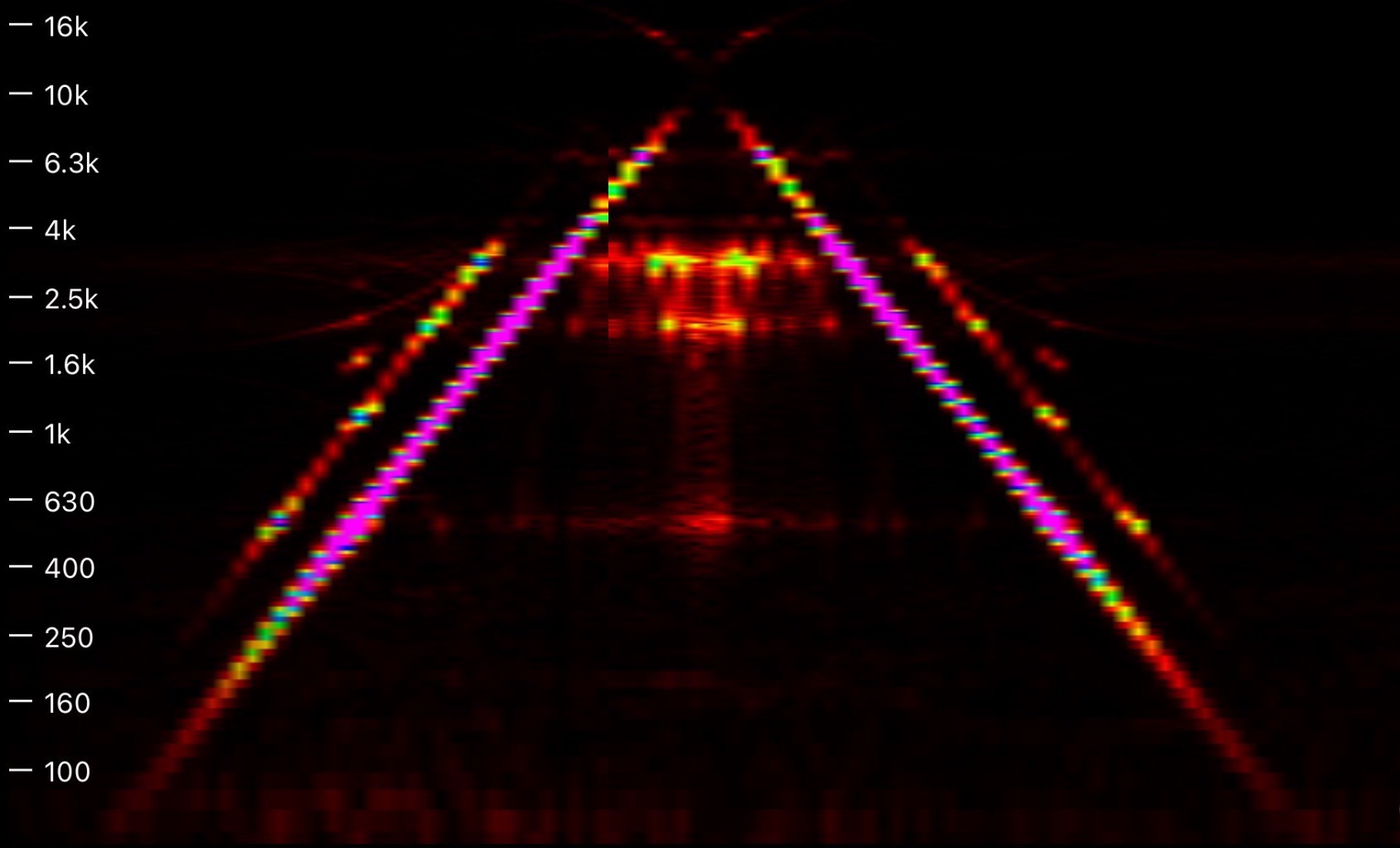
You can see that our amp introduces some serious harmonics. The line you see following on either side of the main frequency is the second order harmonic. The noise in the middle of the pyramid shape is caused by weird harmonics produced when our signal approaches the Nyquist frequency. The PWM technique used to generate the audio may be responsible for some of this noise as well.
Good News
The spectrograph is color coded. The purple areas are the loudest part of the signal, with red the quietest. Happily, the purple region in our spectrograph is between about 400hz and 4000hz, which corresponds almost perfectly with the range of human voice. This means our speaker will produce louder sound in the voice range, perfect for a project all about speech.
In practice, this single transistor amp produces easily intelligible human speech with good volume and relatively low noise.
Having said all that, you could definitely do better. Basically any other amp design will be an improvement on this one. But! Before you try to improve on this design, I find that it produces plenty of volume and fidelity. I encourage you to try this simple version- it might be good enough for you!
*if you think this amp is dangerous please do drop me a note!
Discussions
Become a Hackaday.io Member
Create an account to leave a comment. Already have an account? Log In.