 Steph
StephIf your button is made by Learning Resources or is a similar clone, it likely has a transistor right on its PCB that works great for amplifying audio in the Positivity Pusher. The only problem is that it's a tiny surface mount version, which can be a pain to work with.
Well, actually...
The button has two amplifiers, one for the speaker and one preamplifier for the microphone. I'd love to tell you how to use the amplifier that was designed for driving the speaker, but I can't. Because...
I don't know how.
Depending on what version of the PCB your button came with, its speaker is either connected to a black blob or a mysterious IC for which no data sheet is available. Either way, I can't make it work for me. If you have information about making the built-in amplifier work, I'd love to hear about it. What I can tell you about is...
Misusing Repurposing the Preamp
Take a look at the upper left corner of the PCB, near the microphone. This bunch of components brings the mic signal up to a voltage range compatible with the recorder.
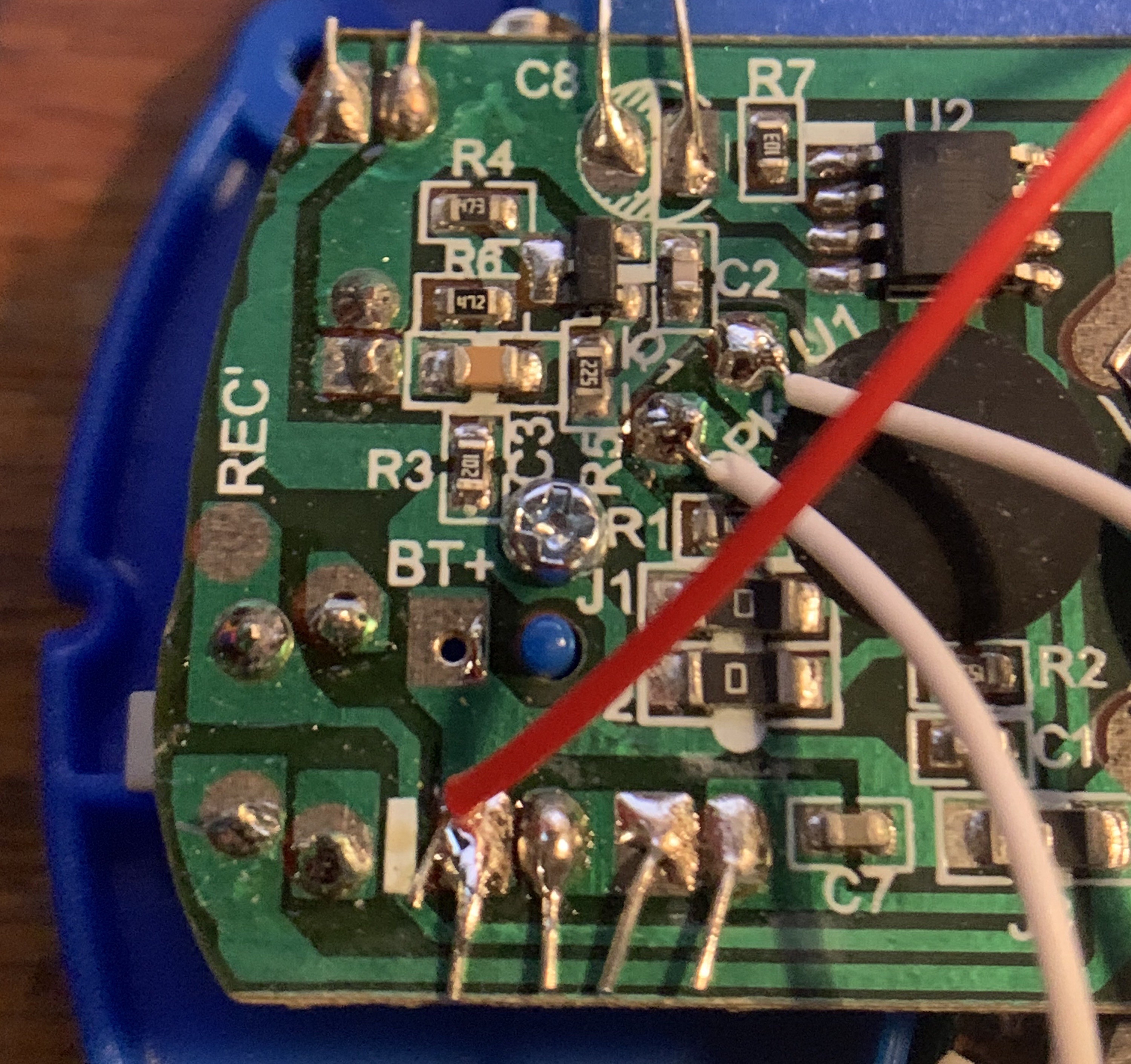
Let's zoom and enhance:
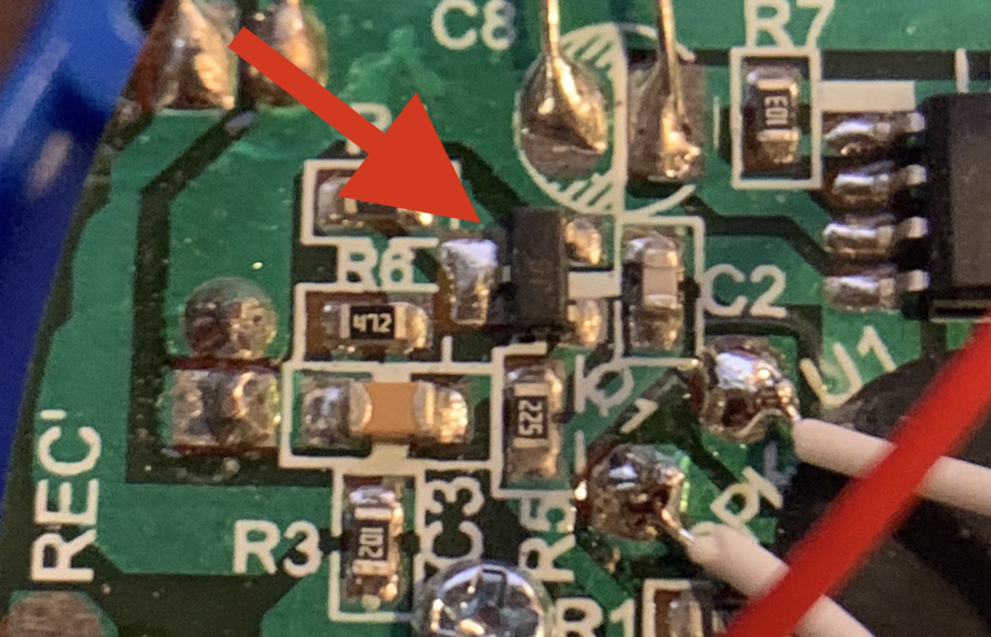
A visit to smdmark.com reveals the the faint "J6" labeled component to be a S9014 Silicon Epitaxial Planar Transistor, Pre-Amplifier, low level & low noise.
Perfect! Ok not perfect.
We're sorta after a high level & high noise type of situation here. But the price and availability of this one can't be beat! I wonder if it can be bent to our will.
It can!
But before we can use it, we have to remove it.
And removing SMD stuff isn't that easy.
Here's what I recommend:
- Tin the tip of a short bit of wire. Put it aside for later.
- Use desoldering wick on the side with the single lead. Remove as much solder as you can.
- Grab the transistor with tweezers.
- Heat both leads on the other side with one big blob of solder.
- Lift the transistor off the PCB.
- Immediately solder the piece of wire from step 1 to the single-side lead. It's much easier to work with and position the transistor this way. It's otherwise very easy to lose and impossible to find if you drop, and there's only one on the board.
As per the datasheet, pins 1 and 2 are the base and the emitter. Pin 3, which has your handle soldered on, is the collector.
To add the transistor to the Pico W:
- Melt some solder onto the GPIO1 pin and the adjacent GND pin.
- Turn the transistor so the J6 label is facing away from the Pico W.
- Solder the transistor base to GPIO1 and the emitter to GND.
- You can now desolder and remove your handle!
Once your Pico W is in place, you'll wire one lead of the speaker to the transistor's collector pin, where the handle used to be.
That's it! You can read more info about the "theory" behind this amplifier circuit here.
Results
Our misapplied preamp turns out to make a very plausible small amplifier! Combined with the 8ohm speaker in the button, our amp can generate uncomfortably loud volumes with manageable distortion and a workable frequency response.
Notes
Some PCBs come with a transistor labeled DAG3 instead of J6. The DAG3 turns out to be a 2SC5343SF transistor, which has the same pinout as the J6.
Some types of buttons, sadly, come with no transistor at all:
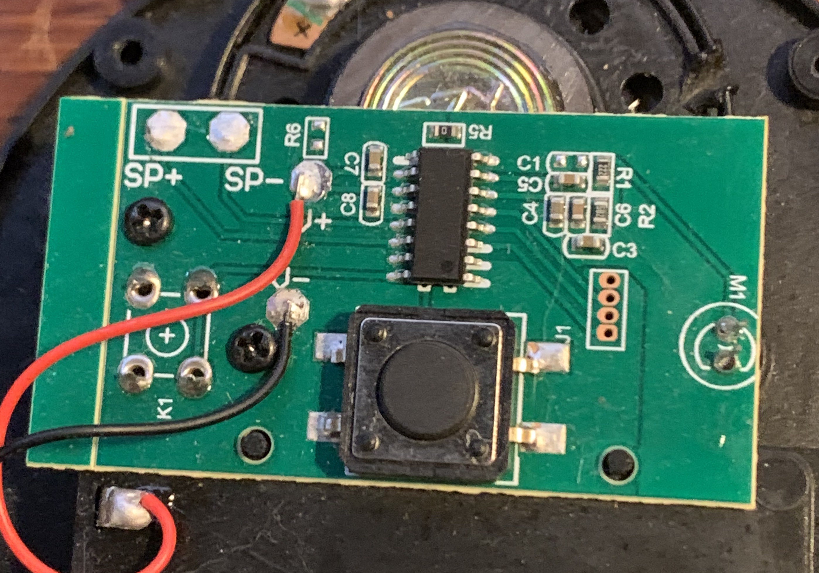
If you've ended up with a button like this, you'll need to get your transistor somewhere else.
Discussions
Become a Hackaday.io Member
Create an account to leave a comment. Already have an account? Log In.