 Steph
StephHatchet Job
How the positivity sausage is made.
At its heart, the Positivity Pusher is a pretty dirty hardware hack. It tries to do a lot of good without a lot of parts. As you'll see in the following section, corners are cut, rules are bent, and on the rare occasion that a datasheet gets consulted, it's ignored.
The upside to this hackery is simplicity.
- The cost is low.
- The needed skills are very low.
- The part count for this project is super low.
The barriers to entry are therefore extremely low.
If you can solder, you can build a Pusher.
...and if you can't solder, this is a great project to learn with.
Remember that the button comes with almost all the pieces you need: the battery holder, both switches and the speaker. Many buttons will even have a surface mount transistor you can salvage if you're an advanced soldering iron user.
Once you've opened the button it's time to get started!
Without a Trace
The first and practically only thing you'll see when you open your button is the PCB. It holds the recording and playback circuitry and the switches for two buttons. You can also see the speaker peaking out from under the PCB. There will be four wires: two for power and two for the speaker.
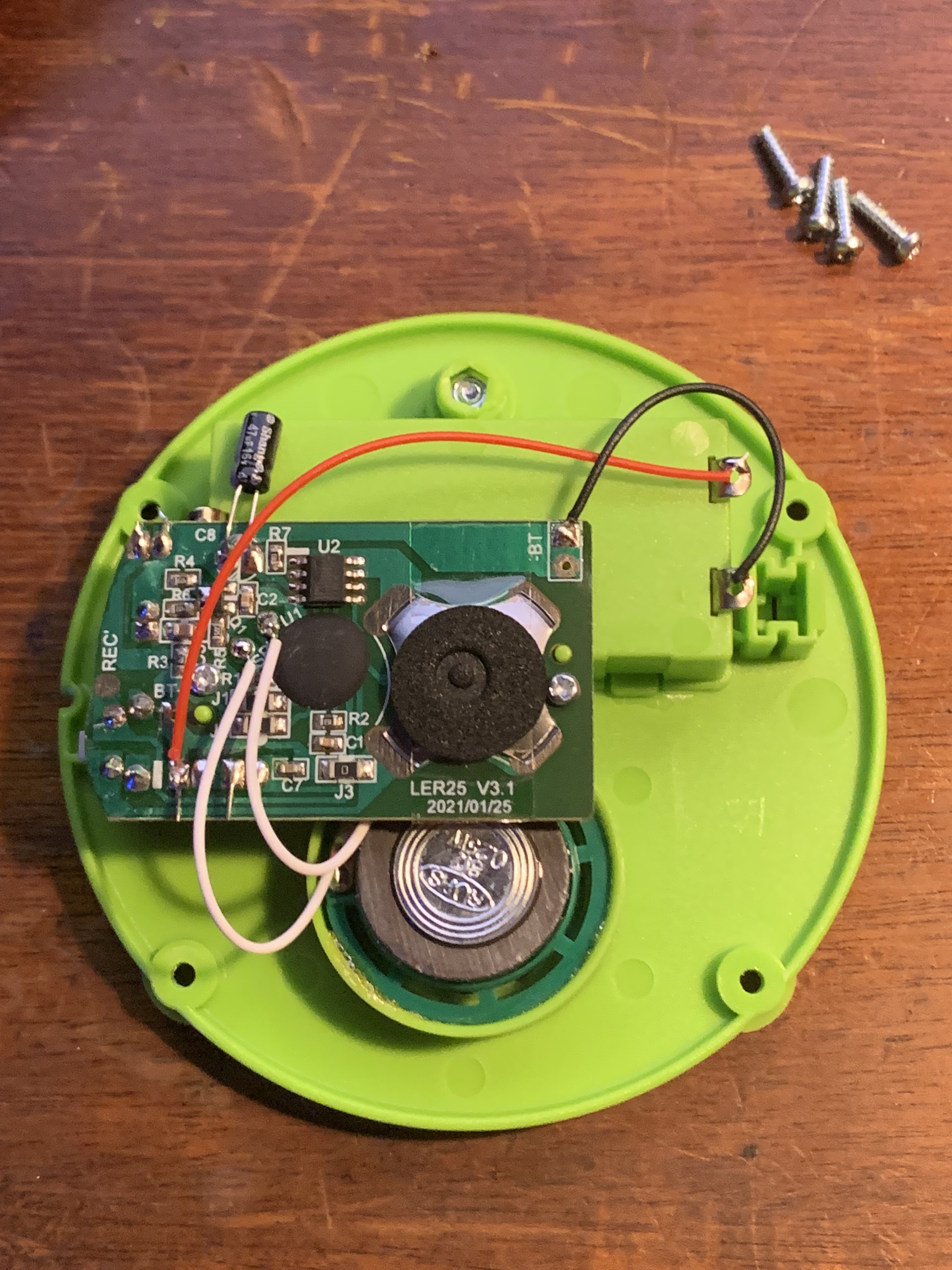
The rest is empty space...
...and nature abhors a vacuum.
Start by desoldering those four wires from the original PCB, leaving them attached to the (empty! It should be empty!) battery compartment and speaker.
Of the stuff attached to the original PCB, we really only care about the switches, and possibly the transistor. Remove the mic by clipping its leads, and save it for another project. Any other components on the board that seem useful to keep in your parts bin can be safely removed, too. If your PCB has a transistor you're planning on reusing, now might be a good time to desolder it.
The easiest way to reuse the switches is to leave the original PCB in place so that it continues to mechanically hold the them in proper alignment with the case. This means we have to electrically disconnect these switches from the original circuit while leaving them physically attached.
Looking closely at the board, it should be easy to see the traces that connect each switch to the rest of the circuit. One side of each switch will be connected to ground, which is easy to identify because it's the largest area of the board. The other side will be connected to a thin trace that runs back to the original processor. Leave the ground side connected, then get something sharp.

Knives Out
Carefully cut through the thin traces with a sharp knife. If you make a mistake and multiple traces, that's ok! Nothing bad will happen at all. Here, you can see the trace leading to the under-mounted side switch, with the arrow pointing to where it has been cut. Also note how the cut extends well into the ground plane. This is fine.
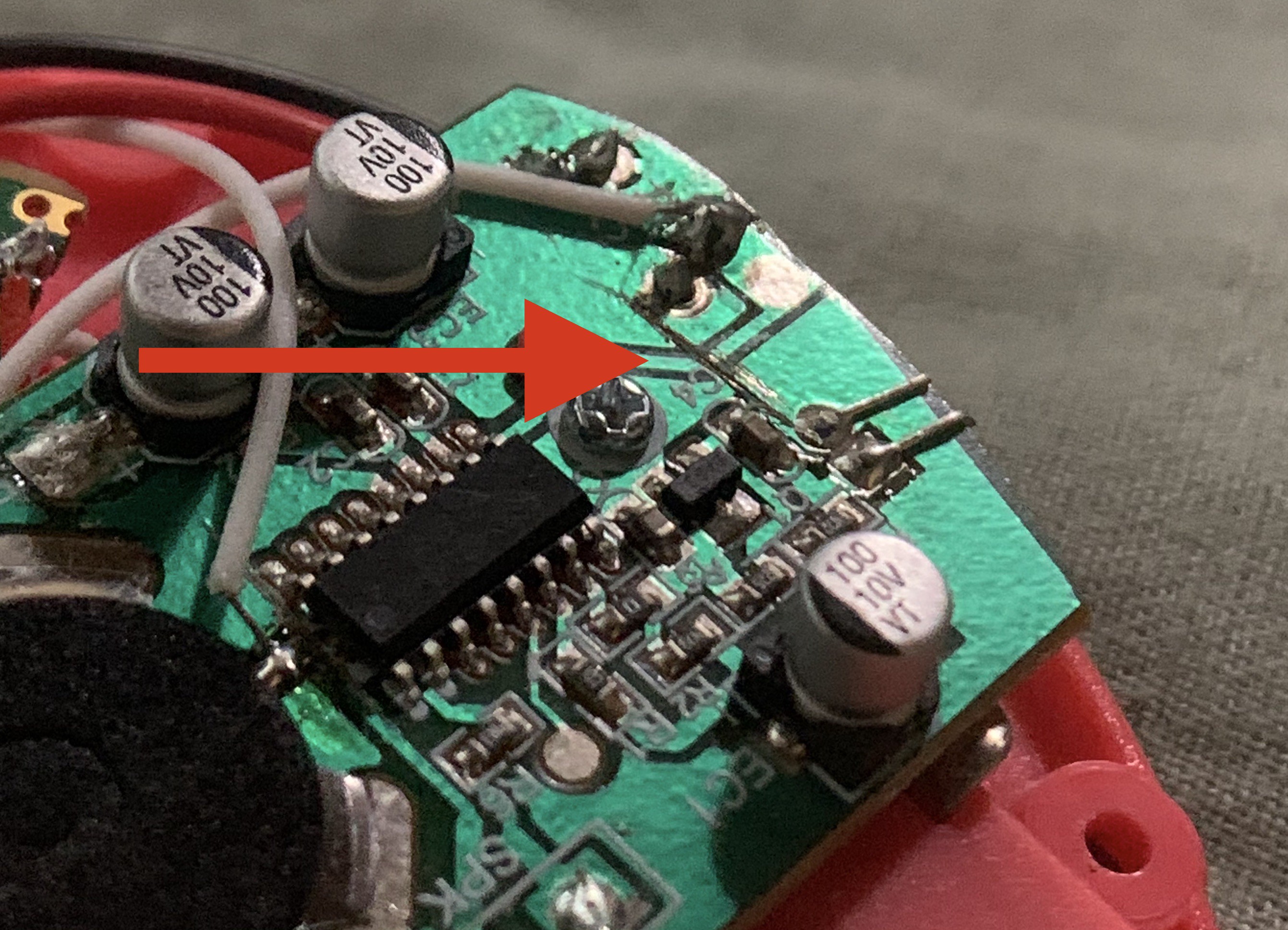
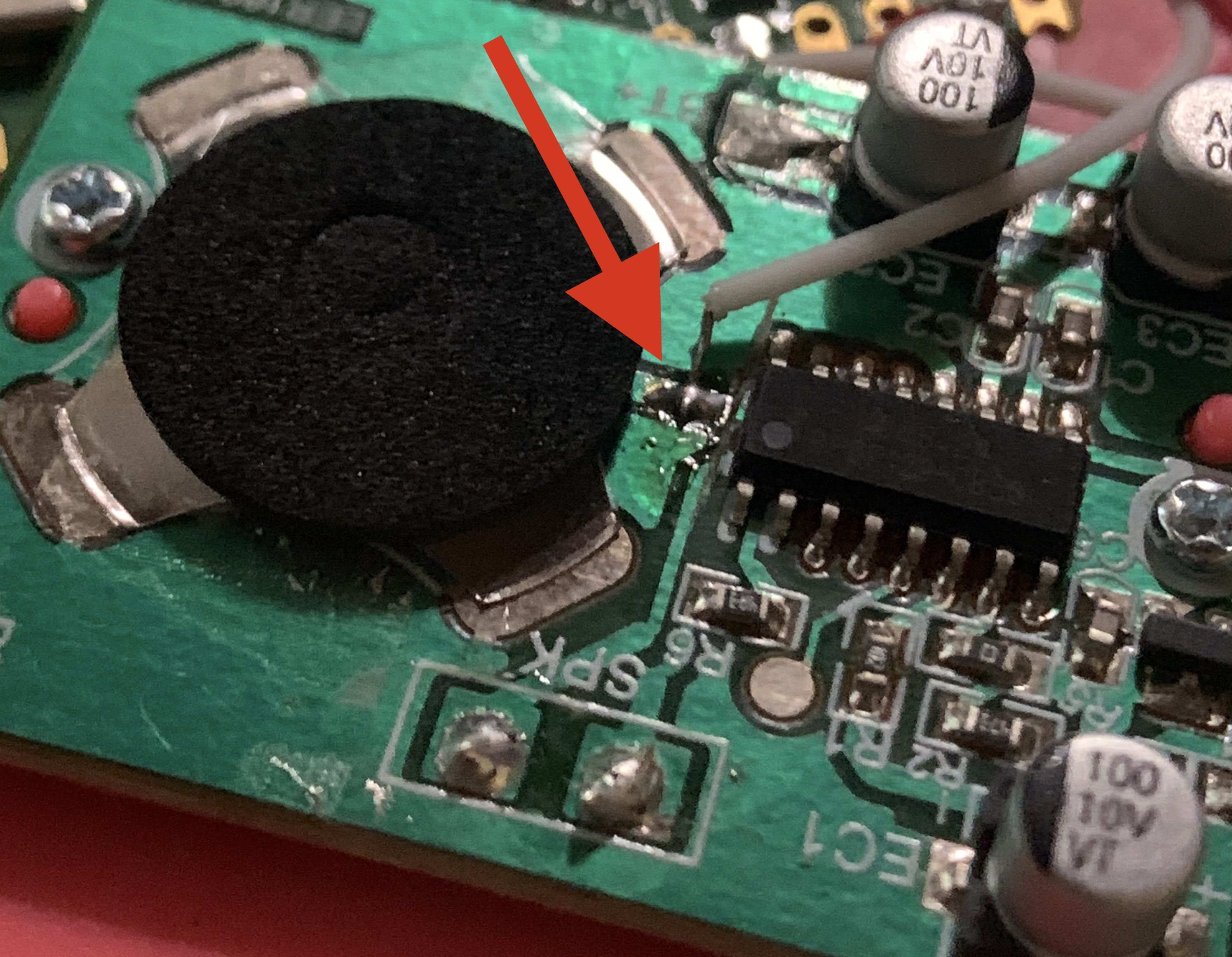
Next we'll add a wire to each switch. Depending on what type of switches your button uses, it may be easy to solder a new wire right onto the pin of the button, as you can see in the photo above. However, some buttons use dome switches that are surface mounted, meaning they have no pins:

If you have a switch like this, you'll have locate the small trace that emerges from the center of the switch and scrape off its green coating to reveal the copper underneath. Then, you'll solder directly to the trace. Here's an example inside a button of mine, with a wire attached to the scraped and cut trace from the center of the dome switch:
Leave the ground pins connected to ground. Next...
We can rebuild him
Now we can start hooking up our Pico W. As you can see in the diagram below, just eight out of the forty pins available on the Pico W get hooked up to anything.
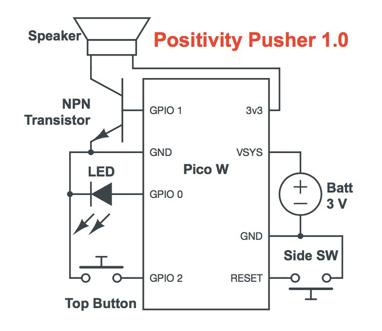
- (please note the pins on the Pico W have been repositioned in this diagram for clarity)
Mr. Transistor
It's easiest to solder the transistor into place before attaching the Pico W to anything else. Transistors all have different pinouts, so be sure to which pins are which for the specific transistor you have.
Start by soldering the transistor's base pin to GPIO 1 and the emitter pin to GND. These pins are direct neighbors so the fit should be easy. If you're using a through-hole transistor, gently bend the collector pin away from the others so that it points towards the center of the Pico W. Leave it disconnected for now.
Time to Cram
In order to fit in the case, the Pico W will slide in, at a cattywampus angle, sandwiched between the top of the speaker and the bottom of the original PCB. This positioning obscures a couple of pins we want to use on that side, so it's best to solder these pins before they get hard to reach.
- Solder a wire to the Pico W's RESET pin, long enough to reach the side or bottom switch.
- Attach the positive wire from the battery compartment to the Pico W's VSYS pin.
- Connect one of the speaker wires to the Pico W's 3v3 pin. If they are labeled, use the (+) wire.
- Solder the negative battery lead to the Pico W's GND pin.
Finally, before you slide the Pico W into place, put some tape over of the metallic back of the speaker to prevent any short circuits from happening. Then, you're ready to slip it under the top PCB. Don't force anything. You may have to temporarily loosen the two screws holding the PCB down in order get the Pico W under it.
Once it's in place, there are just four last connections.
- Solder the negative speaker lead to your transistor's collector pin.
- The RESET pin's wire attaches to the non-ground pin of the side or bottom switch on the original PCB
- The wire from the top button attaches to GPIO 2
- Connect your LED negative lead to GND and positive lead to GPIO 0 through an appropriately sized resistor. If you're up for a challenge, you can salvage a perfectly suitable surface mount resistor from the original PCB.
Discussions
Become a Hackaday.io Member
Create an account to leave a comment. Already have an account? Log In.