 Alistair MacDonald
Hardware
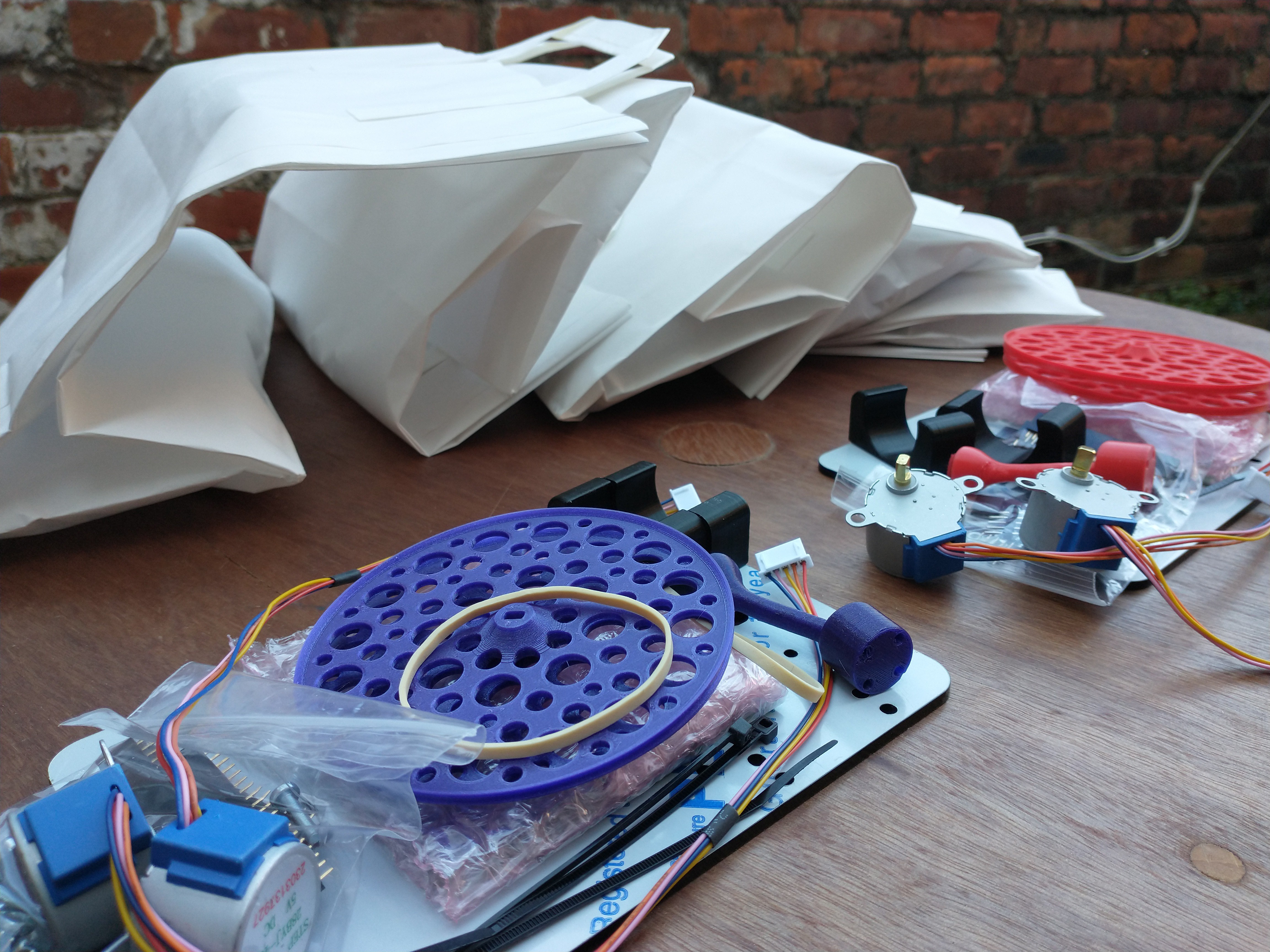
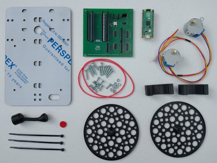
The hardware consists of a main controller board with the Pi Pico compatible board installed, and a chassis with two low cost 28BYJ-48 stepper motors mounted to it. We web interface uses the WizFi360-EVB-Pico and is being ported to the Pi Pico W.
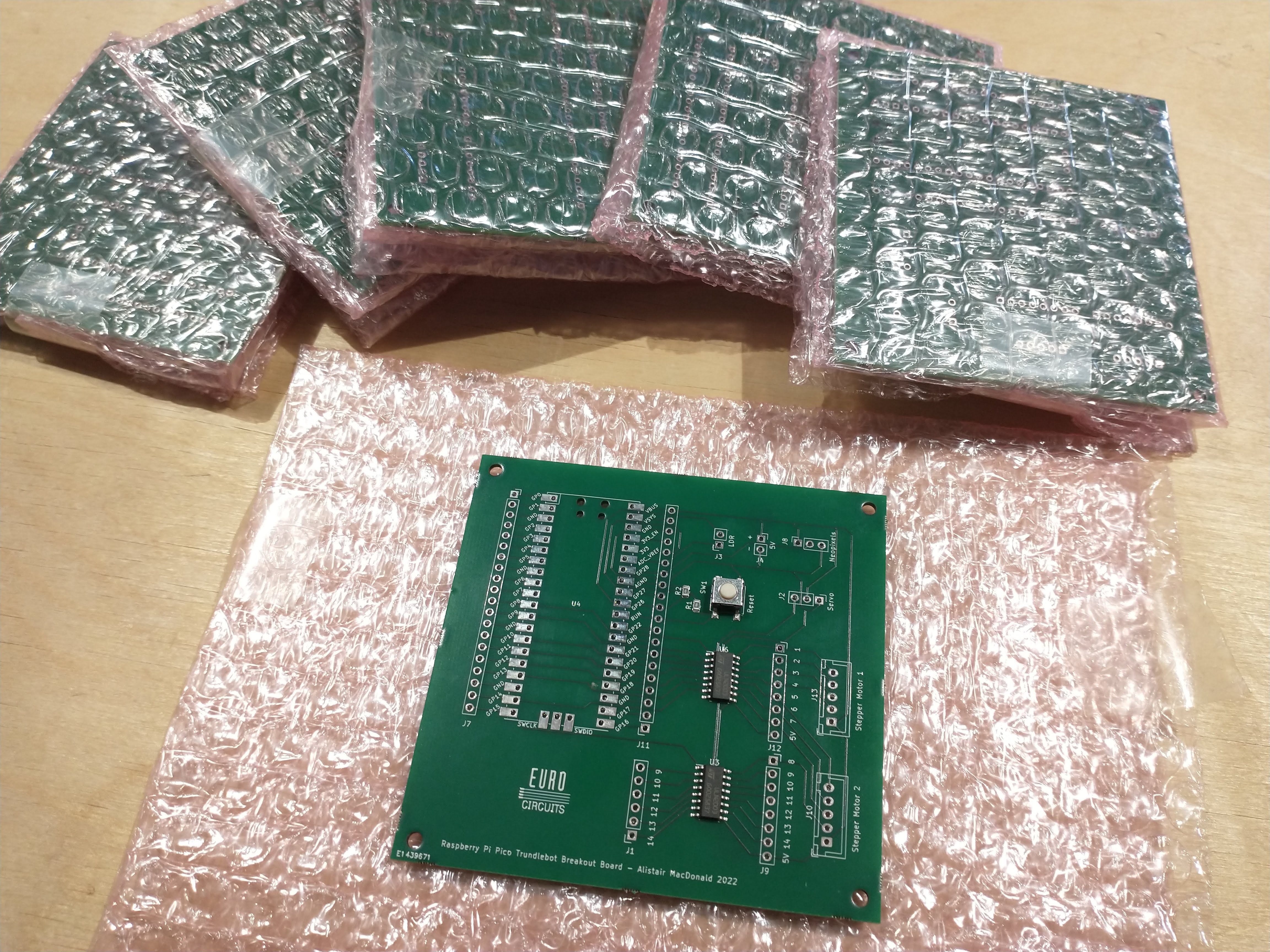
The PCB design files for the controller board are available to download from this page. Most online PCB manufacturers can create a partly-assembled board from these files with all the key components already in place.
The chassis can be laser cut using the DXF file from here, but hand cutting from 3mm plywood is also an option if you do not have access to a laser cutter. The 3D printed parts can be produced on most 3D printers and should be small enough that they can be ordered online at a low cost if printing them is not an option.
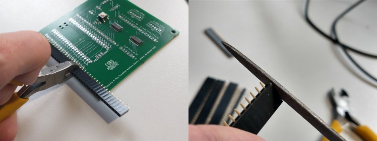
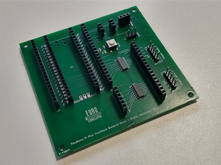
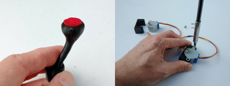
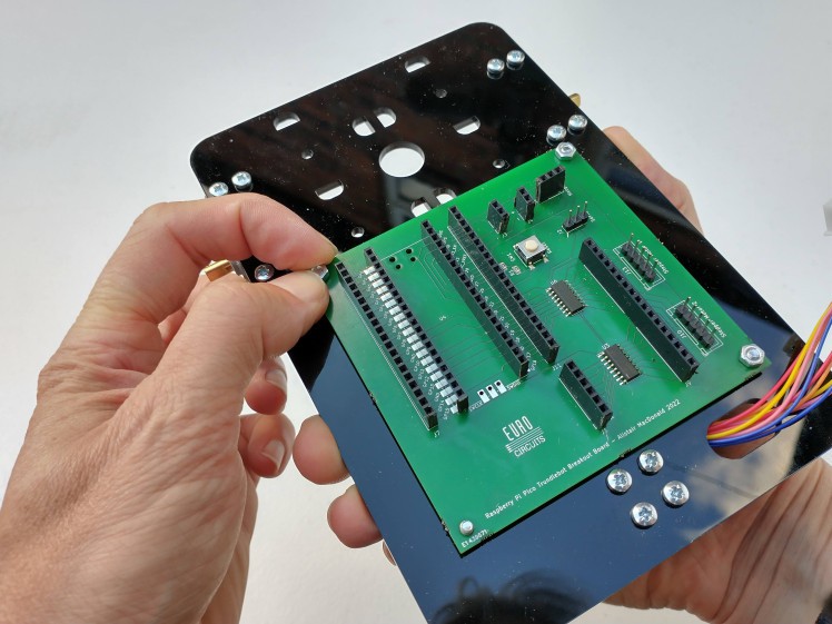
Assembly will take a couple of hours. I have created a separate set of build instructions with photographs. This is also available for download from below.
Software
With education being at the centre of this project it was important that it remain compatible with other Pi Pico educational projects, and that the code all be in Python. To enable this a set of libraries have been created to bring the required WizFi630 functionality natively to Python.
The base library that controls movement is trundle.py. Including this in you project gives some simple calls to move the Trundlebot around.
# Include this at the top of every programme
import trundle

# Move forward 50mm
trundle.forward(50)

# Move back 20mm
trundle.back(20)

# Turn right 45 degrees
trundle.right(45)

# Turn right 90 degrees
trundle.left(90)
Using the WizFi360-EVB-Pico gives full remote control via a drag and drop web portal. The following libraries (available from the GitHub repository) are used.
- wizfi360.py : This handles communication vaa the UART to the WizFi360 wifi module and dispatches callbacks to the rest of the Python code.
- wizhttpsrv.py : An HTTP server that sits on top of the wizfi360.py library.
- trundle.py : The Trundlebot stepper motor driver library that is used to move the robot.
- index.htm : The web app including all the HTML5, CSS and Javascript combined in to one file
- wizmain.py : The main WifFi Trundlebot code that joins everything together
- main.py : This is used to auto start the Trundlebot code.
Before transferring the code you need to enter your wifi configuration towards the top of wizmain.py. After doing this it is recommended you transfer all the files except main.py to the Pico using Thonny. Once transferred run wizmain.py and you will be given a link with an IP address in the console. This is the link to your web app that controls the WifFi Trundlebot by any machine on your local network.
After testing your Trundlebot you can then copy across the main.py. This final file will auto start after being powered, connect to the wifi, and start the web app server.
Web interface
The WizFi Trundlebot is controlled via a drag-and-drop web interface. You have a number of commands to the right of the screen, including forward and back, right and left, and wait.
If you want the robot to turn right then just drag the “Right” command to the list on the other side of the screen and enter the angle you would like it to turn by. Similarly, if you want to move forward drag the “Forward” command to the list and enter the distance. You can reorder the list and drag items back you no longer want.
When you have your commands programmed in you can hit the “Go” button and your WizFi Trundlebot will start to move.
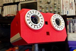
Hopefully you like the WizFi Trundlebot and will have a go at building your own.


 ThunderSqueak
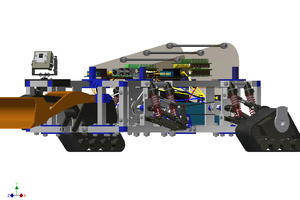
 David Gitz
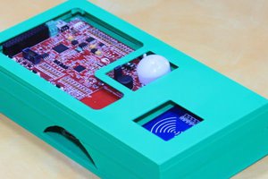
 Inderpreet Singh
 jdelbe
The emphasis on easy assembly and the availability of commonly accessible parts ensures that anyone can build the robot without significant obstacles. Moreover, the project's extendability allows users to customize and enhance the design according to their preferences or combine it with other educational resources and also this article explains what it is, and why it is important The compatibility of the design with various Raspberry Pi models and the WIZnet WizFi360 expands its versatility and potential applications. Overall, this project holds promise in promoting programming education and hands-on learning experiences with robotics