 M. Bindhammer
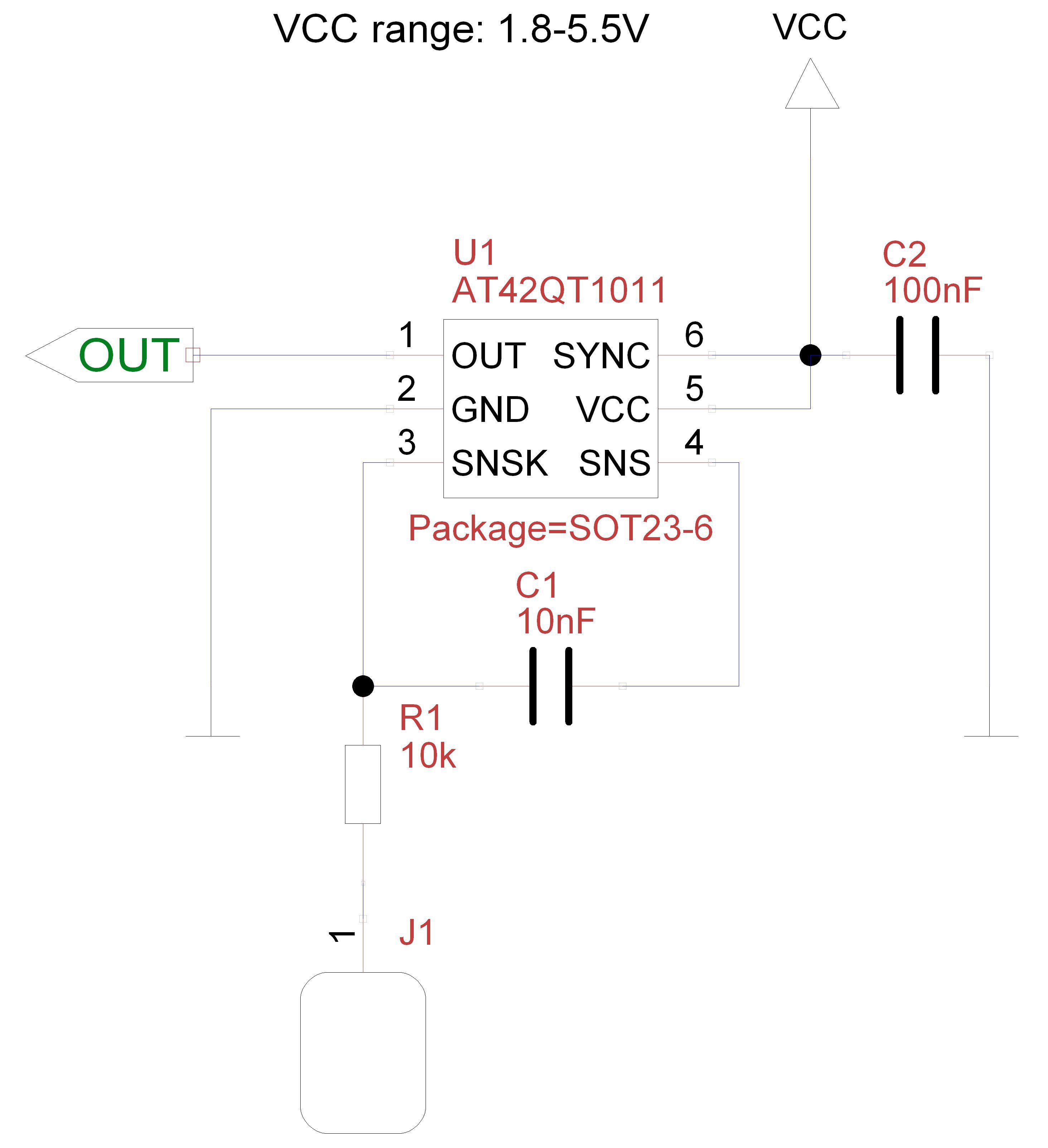
The first PCB I had to design is the one for the touch sensor. I use an AT42QT1011, which is a capacitive sensor. The wiring is very simple.
The board design is just as simple. To not interfere with the touch sensor, I did not use a ground plane. The datasheet states in this regard: Metal areas near the electrodes will reduce the field strength and increase Cx loading and should be avoided, if possible. Keep ground away from the electrodes and traces.
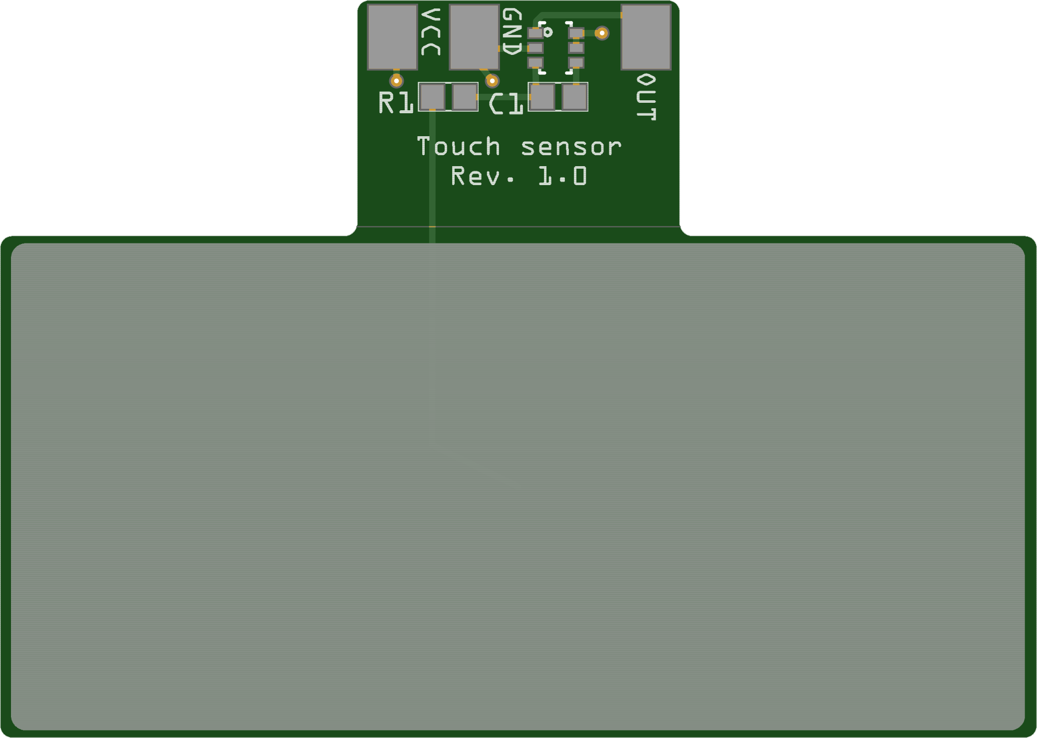
The only component that is a bit difficult to solder by hand is the AT42QT1011. You need a magnifying glass and backlight to find the pin 1 ID.
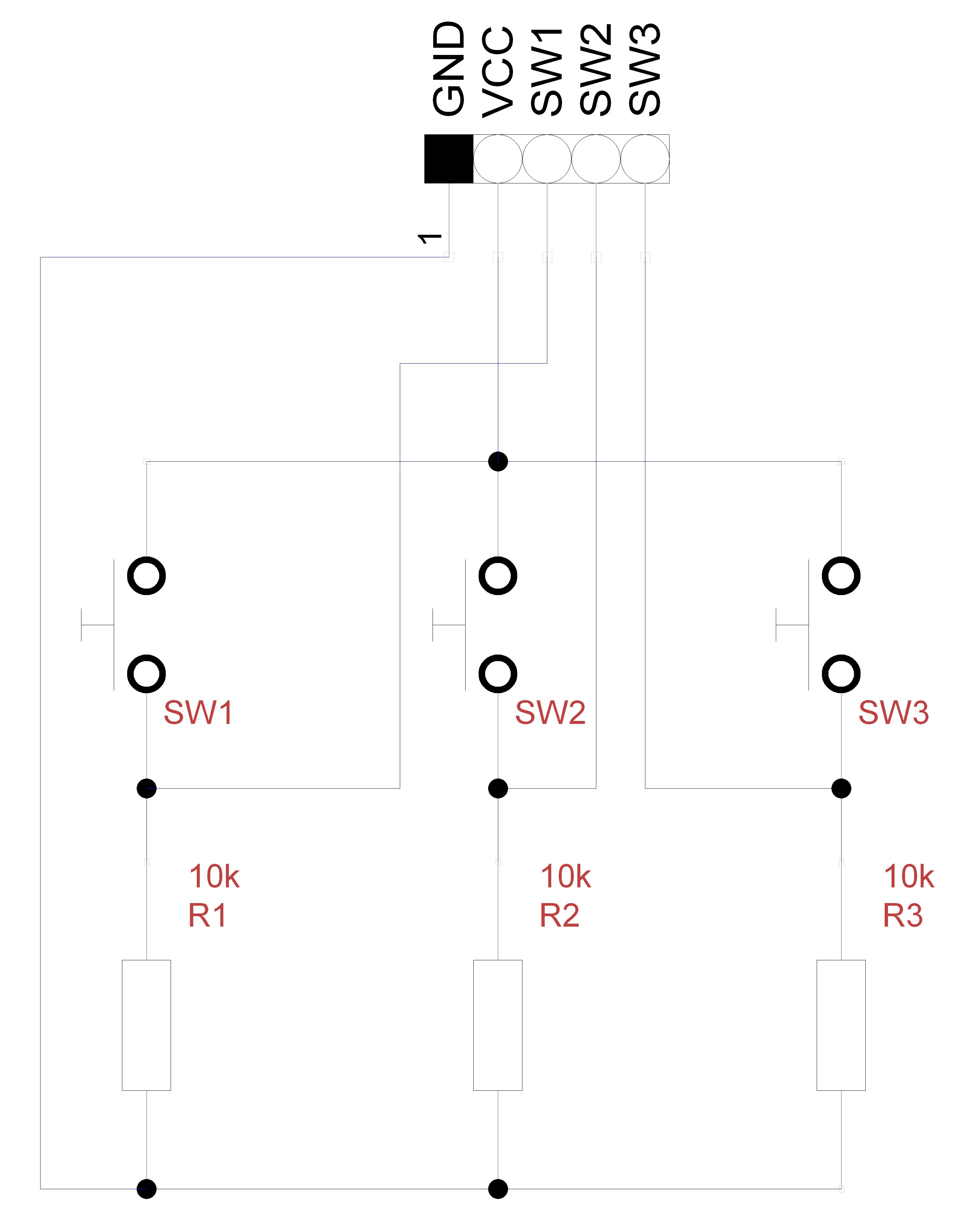
The second PCB for the robot that I designed is the one for the three push buttons.

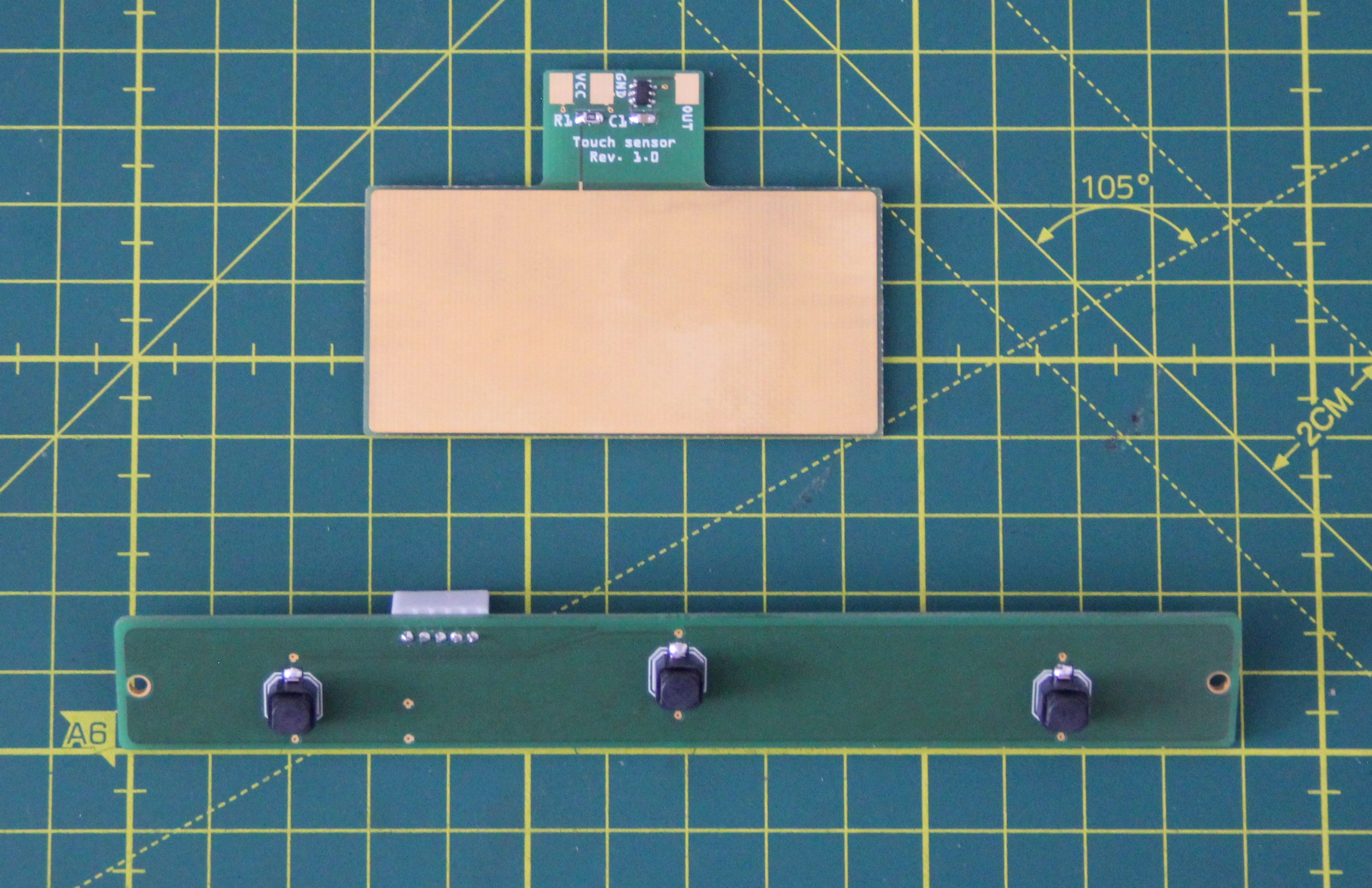
The touch sensor is very sensitive. When I get closer than 2cm with my finger, the circuit already reacts. I also put my pills on the touchpad. Fortunately, they contain too little water to react. By decreasing the value for C1 we can make the sensor less sensitive if need to. In my case, I had to change the value of C1 to 4.7nF.
The third and last PCB we need is a shield for the Arduino Due. All connections are broken out, it supplies 5V with up to 1.5A for the servos and has a DS3231 Precision RTC and a backup battery on board.
For the shield, the LDO was first soldered using solder paste and a hot air gun, since the GND solder area of the LDO in the D2P package is not accessible in any other way. The remaining components were soldered by hand.
On the bottom side, you can see the female pin header for the SPI connection. There is no other way to make the SPI pins accessible on the Arduino Due.
Finally, the PCB was cleaned of flux residues using isopropanol and a discarded toothbrush.
Discussions
Become a Hackaday.io Member
Create an account to leave a comment. Already have an account? Log In.