 Mehrdad Majzoobi
In this project log, I will discuss challenges I faced during the design and prototyping the LED ring feature of Ubo pod, things I tried, and the solutions I came up with.
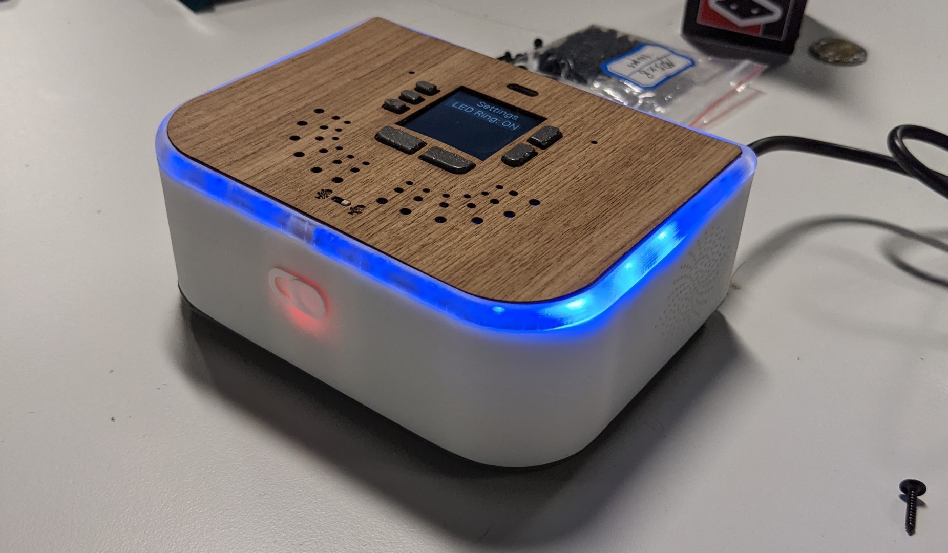
In order to display notifications and visual cues at a distance I had decided to include an RGB LED ring to Ubo pod (similar to many other smart home product). This feature would allow developers to effective communicate notifications to users silently and catch user's attention.
Choosing the LED component
The first decision I had to made was which type of LED component I need to select.
I knew that using a non-addressable LED was not going to be a feasible choice here since in that case I had to deal with addressing them with another IC and routing 4 wires to each LED light would become a nightmare.
Therefore, I narrowed down my search to different types of addressable RGB(W) LEDs. The two main contenders were Neopixel and Dotstar LEDs. There's an awesome comparison of these types of LEDs posted by Adafruit on this page.
Since I needed to add a bunch of LEDs to form a full ring, the cost per LED was an important factor. I ended up putting 27 LEDs on the PCB!
I had previously used Neopixels in other projects and I had an inclination from the get-go to use them. However, there were a few things that bugged me about them and a few things that I liked.
Basically, the main cons for Neopixel LEDs were:
- PWM driver conflicts with RPi sound card
- Requires DMA and application requires super user privilege on Pi.
and the Pros were:
- One Data-In and Data-out line. Makes routing easier
- Very common and comes in variety of packages
- Low cost
On the other hand, DotStar LEDs had the following pros and cons:
Pros:
- No need for DMA and could be driven for regular GPIO pins
- No conflict with Pi audio
Cons:
- More expensive than Neopixel LEDs
- Less variety and options for packaging
- Routing 2 Data-in / Data-out lines would take more space
The cost factor and the existence of more packaging options finally convinced me to stick with Neopixel in my design, specially since I was adding a separate audio driver chip for HiFi audio and was not relying on Pi low quality PCM audio moving forward (considering on-board soundcard conflict issue).
Next challenge: Light Diffusion
This was a seemingly easy task at the beginning, however, a special design constraint turned it into one of the most challenging optical design work that I had undertaken before. The design constraint was to: diffuse RGB LED visible light to remove hotspots but let IR light pass through with minimal loss. The constraint stemmed from the decision to place the IR receiver sensor and transmitter diodes behind the same light ring.
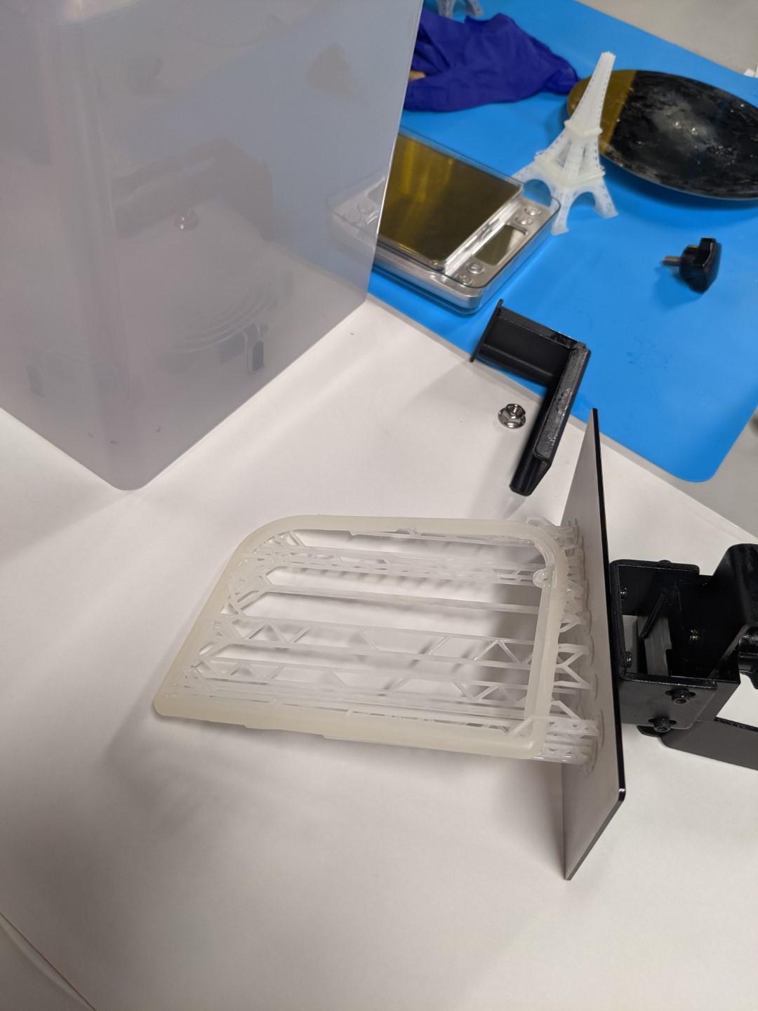
The picture below shows the first prototype. In the first prototype, I placed both the right angle addressable Neopixel RGB LEDs, InfraRed (IR) receiver sensor, and transmitter diodes on the edge of the PCB.
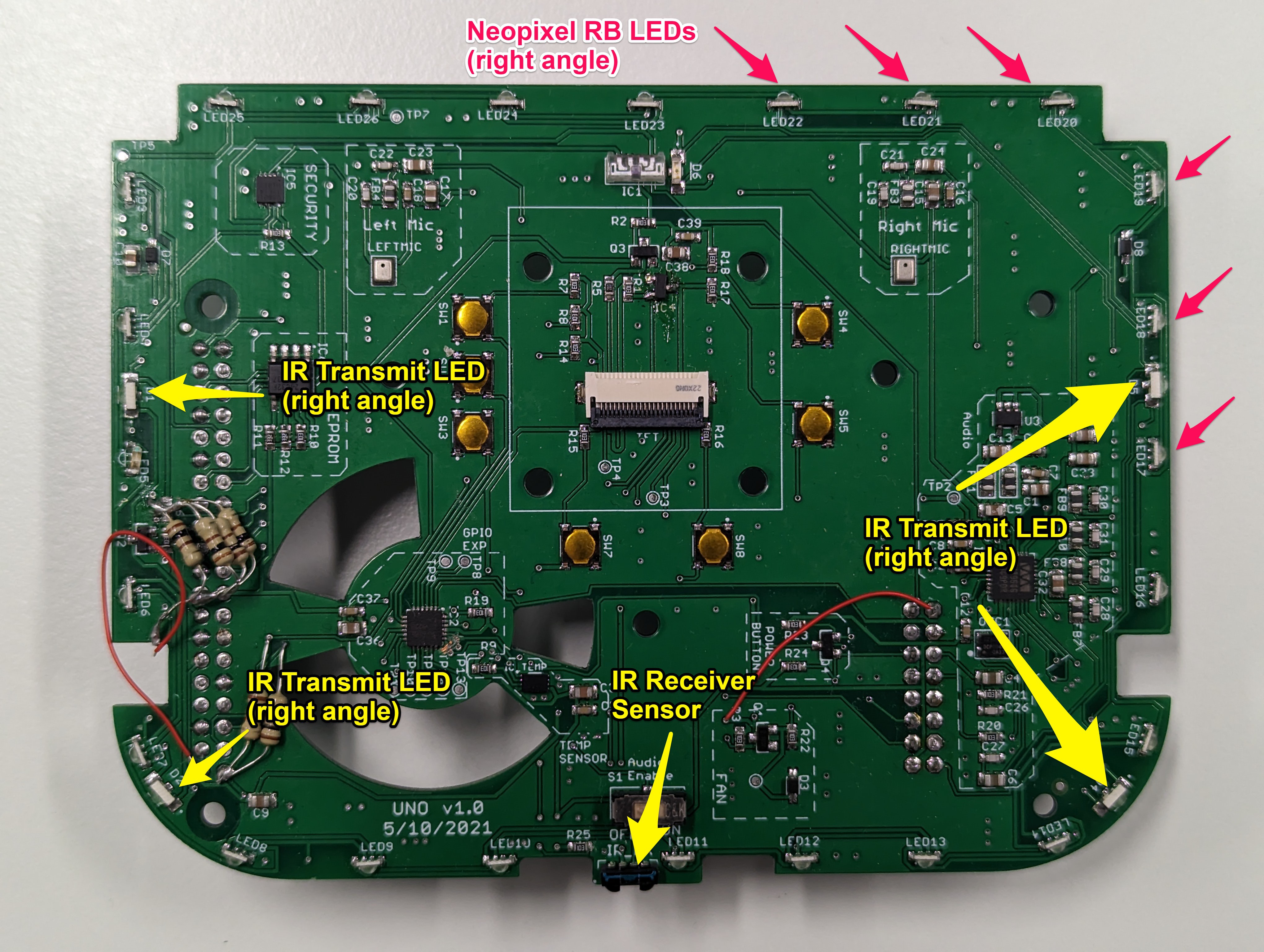
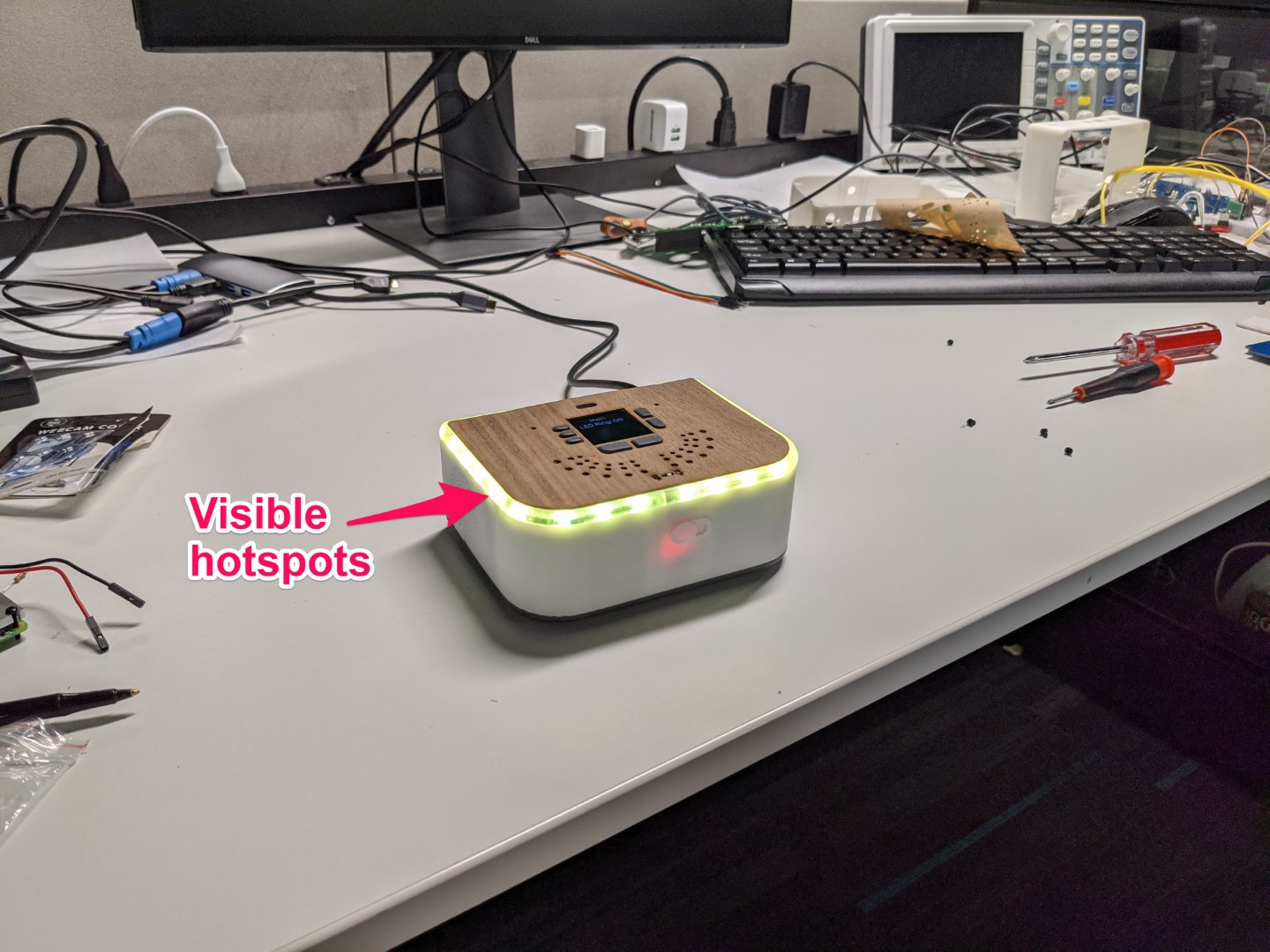
Since the RGB LEDs were too close to the LED light diffusing ring, this created visible hotspots and LED lights were not properly diffused.
To address this issue, I need to do several things (combination of following actions):
- Move back the RGB LEDs on the PCB for better diffusion
- Try top view LEDs instead of right angle so that light does not hit the ring directly
- Two-stage diffusion for RGB LED and single-stage diffusion for IR (more info on this later)
- Make the ring opaque (but not too opaque to block IR signal and decrease IR range)
The idea was to try to diffuse the RGB LED light as much as possible without increasing the opacity of the light ring material. In other words, increasing the opacity of the light ring material had to be the last resort since it would affect the IR light signal strength and lower IR range.
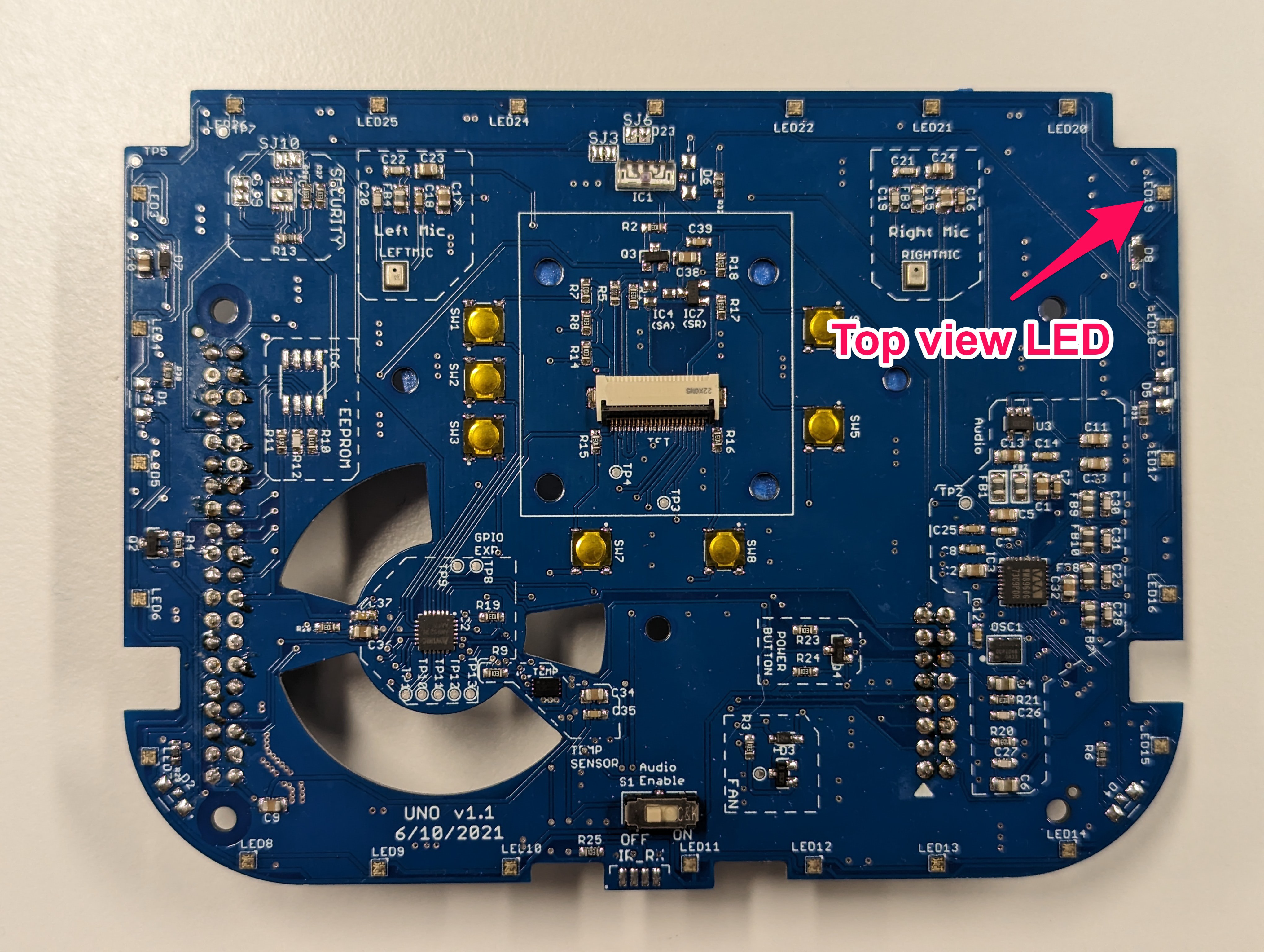
Since moving back LEDs required major change in PCB layout, I decided to try changing the LED type first to top view from side view first. This required only a change in LED footprint and I could spin out a revision very quickly. The picture below shows the PCB revision with this change:
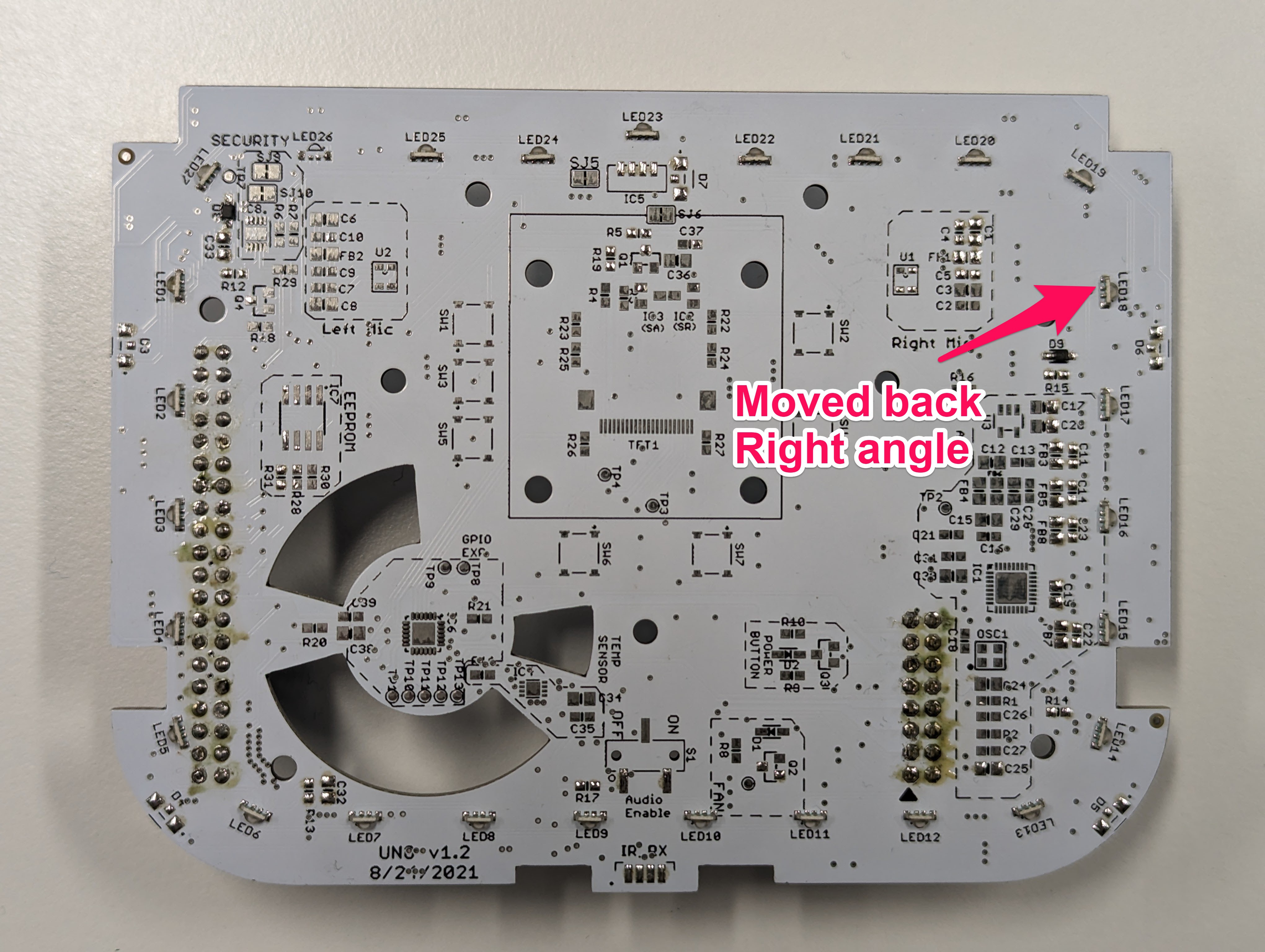
This change improved the hotspots by a small degree but it was not enough. So I decided to change the position of the RGB LEDs. The picture below shows the PCB revision with right angle LEDs moved around 6mm back from the previous position. Due to other design constraints, this was the maximum distance I could move back the LEDs on the PCB.
This change further improved the diffusion and the hotspots were less pronounced but I was not content with the end result especially if the ring was too transparent. So I decided to explore a two stage light diffusion.
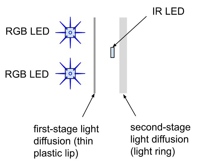
Two-stage light diffusion:
The picture below illustrates the idea for two-stage diffusion. To implement this idea, I added a thin lip (barrier) on the white plastic top cover right in front of the RGB LEDs to set up the first diffusion step. In this implementation, the IR LED light only gets diffused by the second stage diffuser (translucent ring) which does a very small amount of light diffusion. The main light diffusion is performed by the thin plastic wall in front of the RGB LEDs.
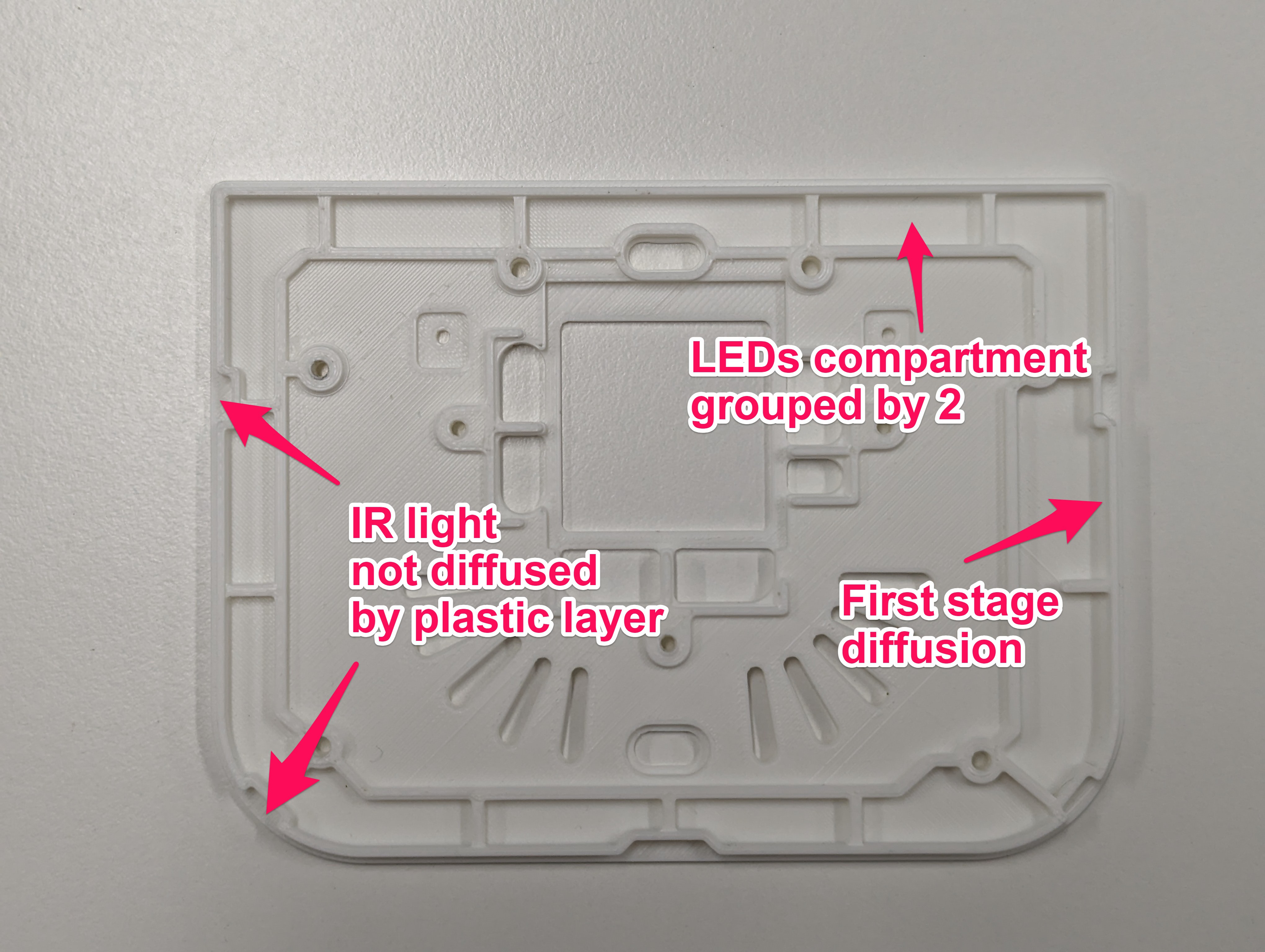
The picture below shows how this is implemented using the top white plastic cover:
I experimented with several two-stage diffusion designs before settling on this design. I still believe there’s more room for improvement for better light diffusion here.
Light diffusing material
One of the challenging aspects of prototyping was experimenting with diffusion level for ring material. Initially, I 3D-printed the light ring with Formlabs 2 SLA printer using clear resin. However, this only resulted in a fixed degree of light diffusion which was not possible to control. Another problem was that no matter what light diffusion property I get with resin, I may not be able to reproduce that with injection molding plastic material. In other words, I needed to experiment with real material eventually and the resin could only give me some indication of desired level of light diffusion.
The first technique I used to control the diffusion level / opacity was to try to mix clear and white resins with different rations. Formlabs 2 3D printer posed some challenges to print with custom resin material since (a) Formlabs is tuned to work best with its own resin system (b) I had to use a new tank for this experimentation and It was possible to damage the tank. Due to such limitations, high-cost, and overhead of such experimentation, I decided to buy a cheap Creality SLA printer. This way, even if I messed up the FEP or the tank, I could replace the FEP. The cost of resin was lower and I could only mix the amount I needed to print and not much more. Lastly, I had more control over printing parameters.
I tried different mixing ratios (such 20:1 and 10:1) to get various degrees of opacity. It turned out that the 10:1 ratio did a good job of diffusing the LED light while passing through IR with minimal loss.
Injection molding
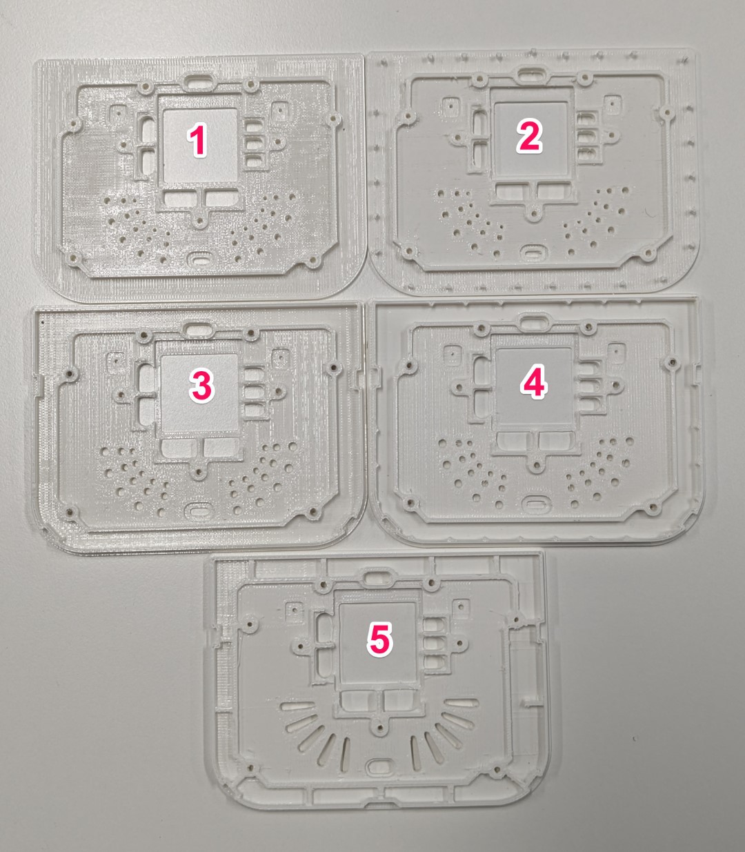
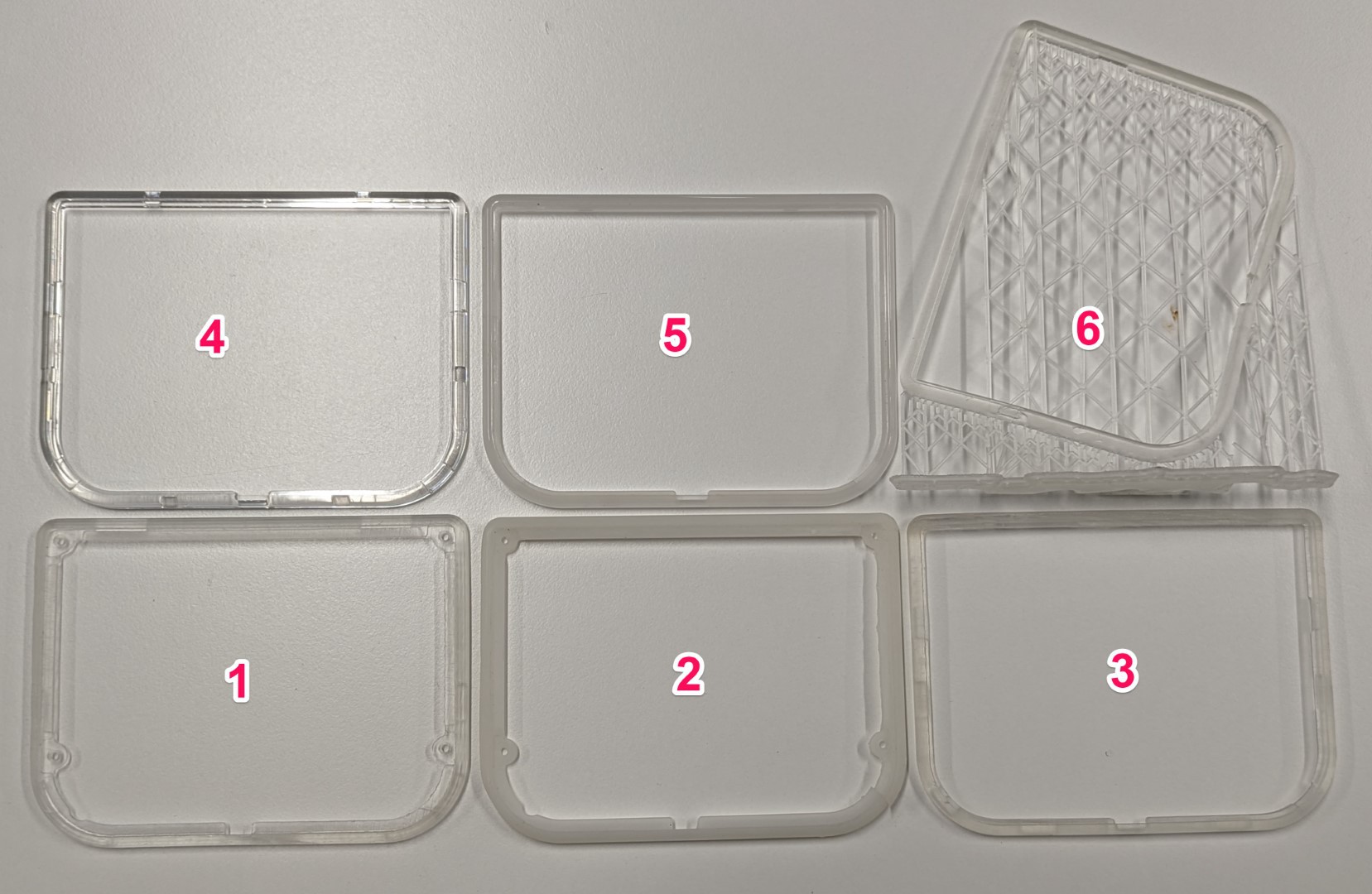
After getting some more confidence about the design, I decided to make my first injection molding tool for Ubo. This was a bit scary at first due to the high cost of injection molding, but it was the only way I could measure exact characteristics. It is very common to use Polycarbonate (PC) with polished surface finish for lighting applications. I decided to make the ring with two types of PC (1) clear (2) 95% translucent. Rings number 4 and 5 in the picture below show clear and translucent rings respectively.
Now with the real material in hand, I needed to measure the loss in IR signal with each type of PC material used.
IR testing range
The image below shows the setup for measuring the IR transmit range. In this setup, I sent on/off commands to the TV and kept increasing the device distance until the TV stopped receiving the command. I repeated this experiment under three set-ups (a) no light ring assembled, (b) clear PC light ring, and (c) translucent PC ring assembled.
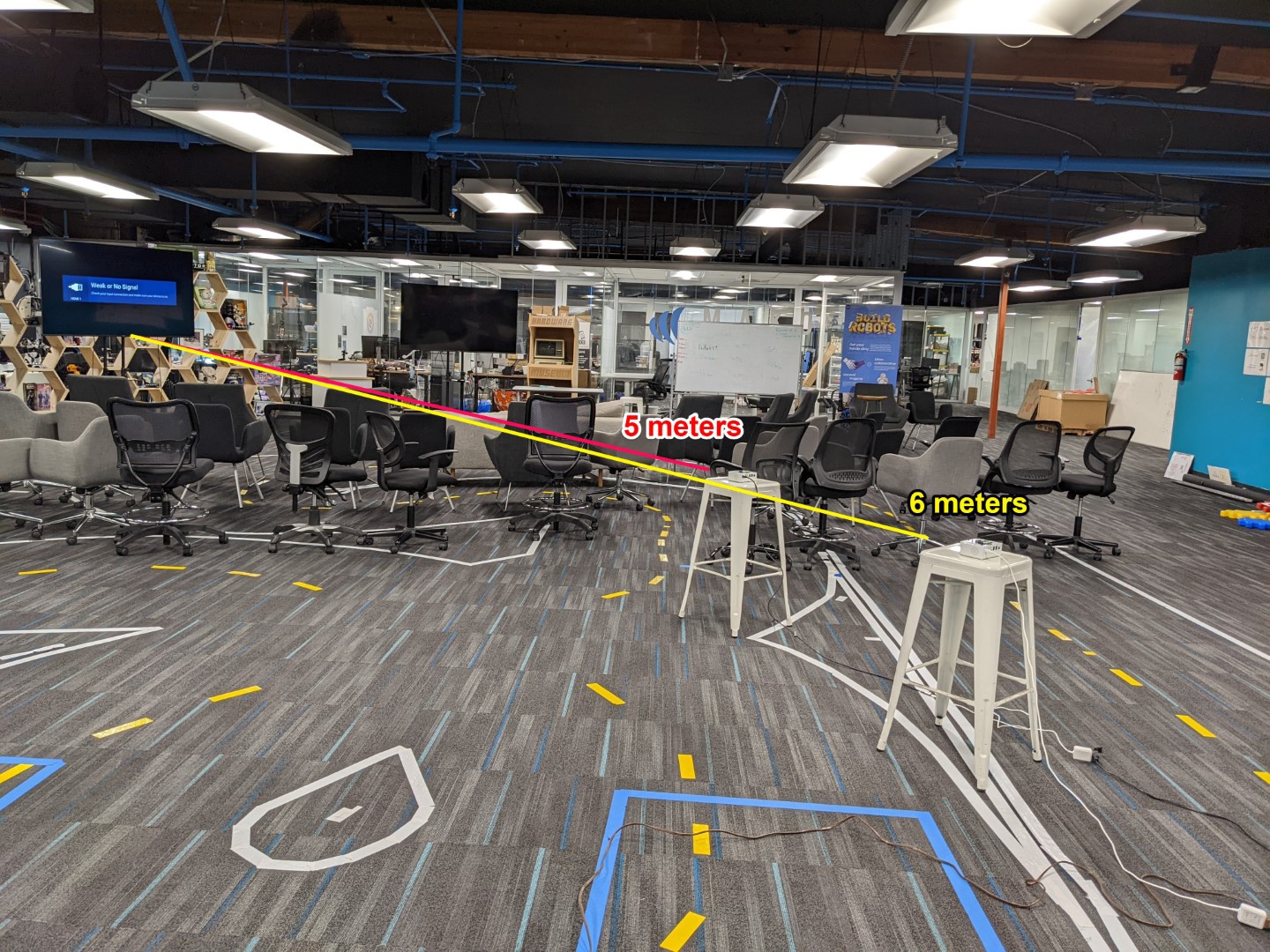
The IR range measured for cases (a) and (b) were identical as expected at 6 meters. The distance measured under setup (c) only showed 5-10% reduction to around 5.5~5.7 meters. I was overall content with the end result.
If you have any questions, please do post it on the comment section below and I will reply asap. There might be some more information that I might have left out in the project log but I will update the log to include them.
Discussions
Become a Hackaday.io Member
Create an account to leave a comment. Already have an account? Log In.