 Krzysztof Pochwała
Concept
The idea sparked a few weeks ago, to create as simple as possible (hardware-wise) robot, that can be used to learn and teach ROS concepts on a real hardware. Price point at target is less than 50$. Given current availability and prices of ARM SBCs that can run ROS (e.g. Raspberry Pi) embedding one in a robot was not viable option. What if the robot itself was dumb effector, and its brain was running on a PC, that everybody has? This way, the electronics and firmware would just subscribe to and publish data to the way beefier computer, and on this computer we'd have virtual agent that looks like a real robot for the end user. Mandatory thing on a robot that can localize itself in the world is odometry. Unforntunately, encoders with proper resolution for the task can cost a significant amount of money, thus an idea of external localization was born - e.g. external camera that looks at the robot (a webcam or a smartphone with RTSP stream app).
Odometry of a robot is based on Aruco markers in the world space and on the robots themselves. Two markers set the world coordinates, and relative to those markers robots are positioned. Multiple robots can be tracked using single camera.
Additionaly, usage of absolute tracking enables possibility to create virtual sensors for educational use. Having real position at any time, we can calculate derivatives (angular velocity, linear acceleration) and output values that normally IMU would. Then publish those faked values as IMU messages for students to write their own implementation of sensor fusion algorithms.
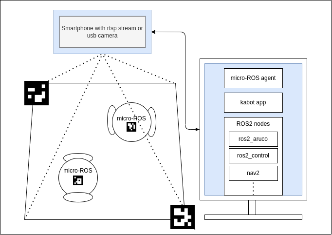
Concept overview diagram.
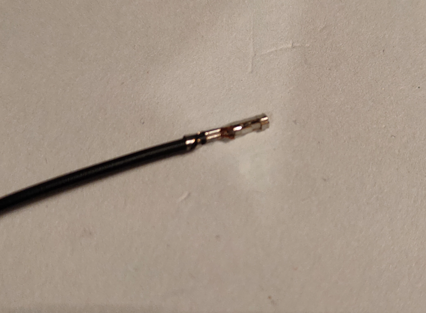
Another thing that any robot needs are environmental sensors. There is such variety of them, from simple light sensors, trough Time-of-flight distance measurement ICs, to cameras so embedding them all on the main board would drive the cost significantly, and even not all scenarios would be covered. Given that, an expansion port that lets user access a bunch of gpios is present on the main board.
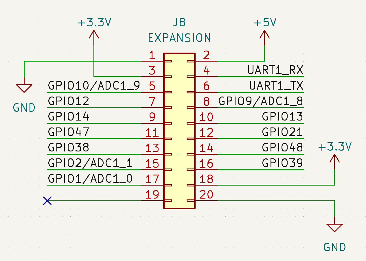
Excerpt from schematic - expansion connector.
Hardware
Bones:
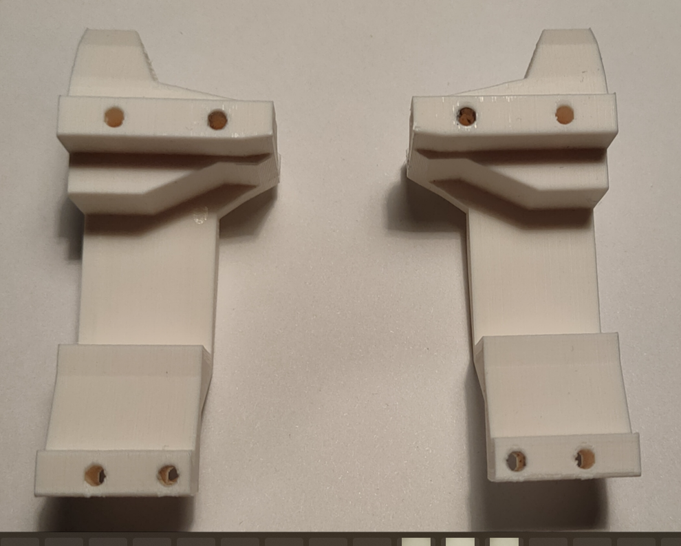
All of the structural parts are designed for FDM printing. Wheels, base, cell holder - PLA will do. For the tires, standard O-Ring seals are used, as they are easily available for a cost next to nothing.
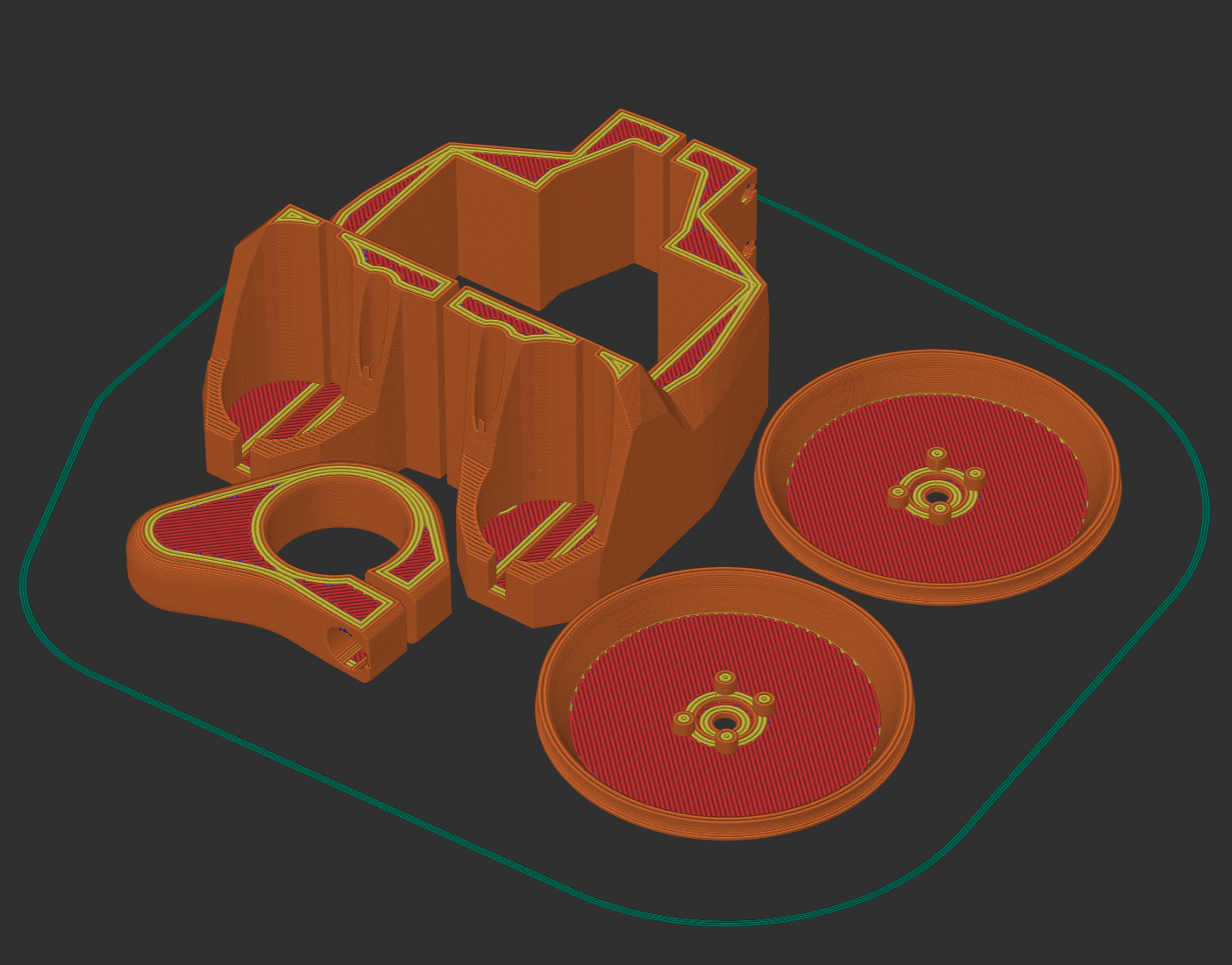
Plate of all printed parts.
Muscles:
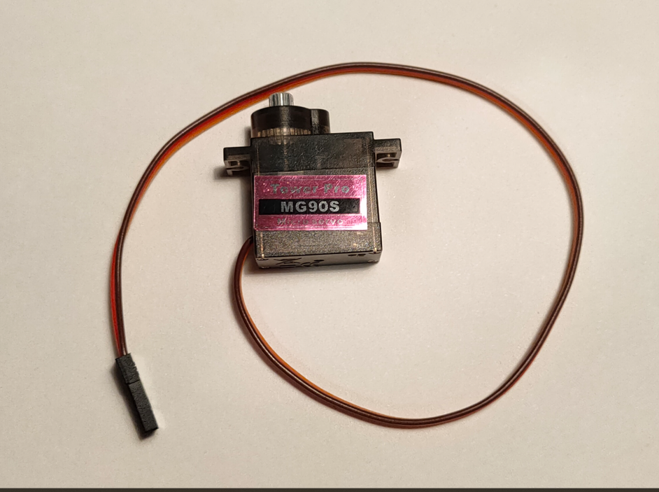
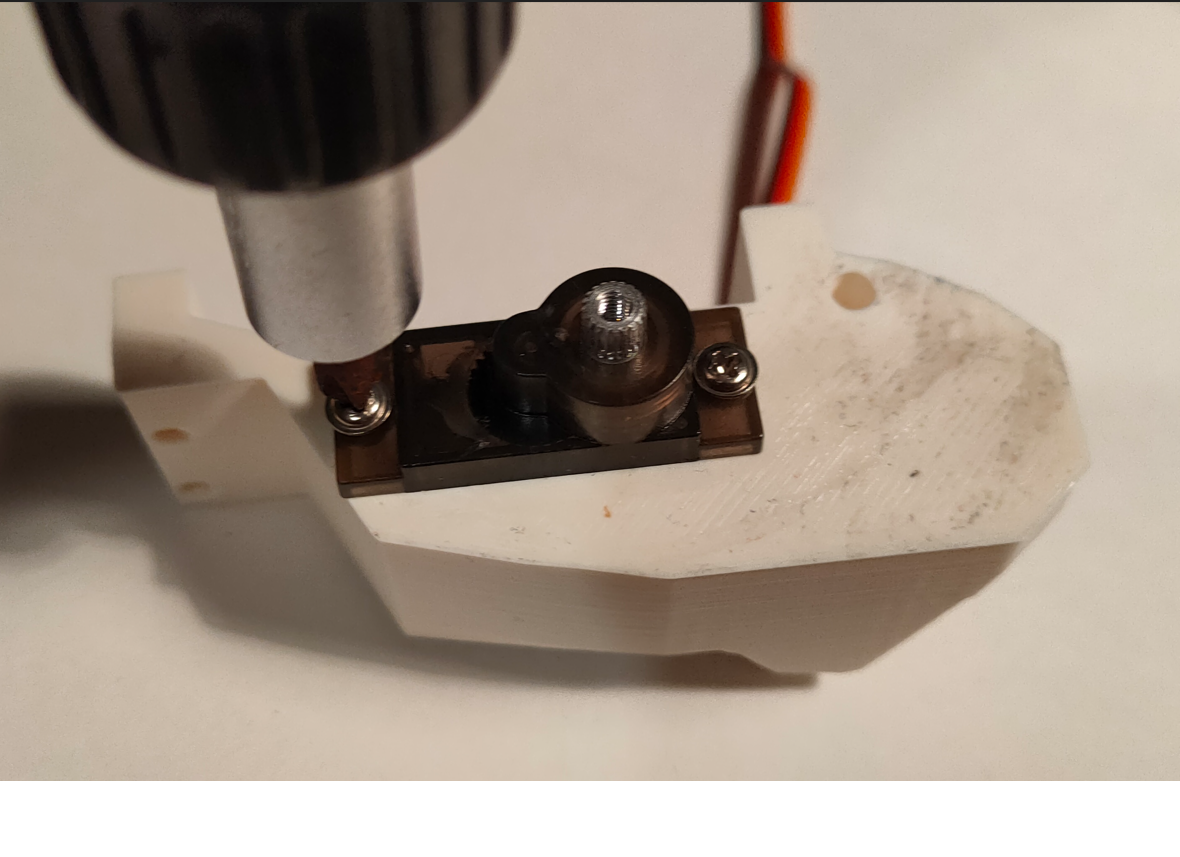
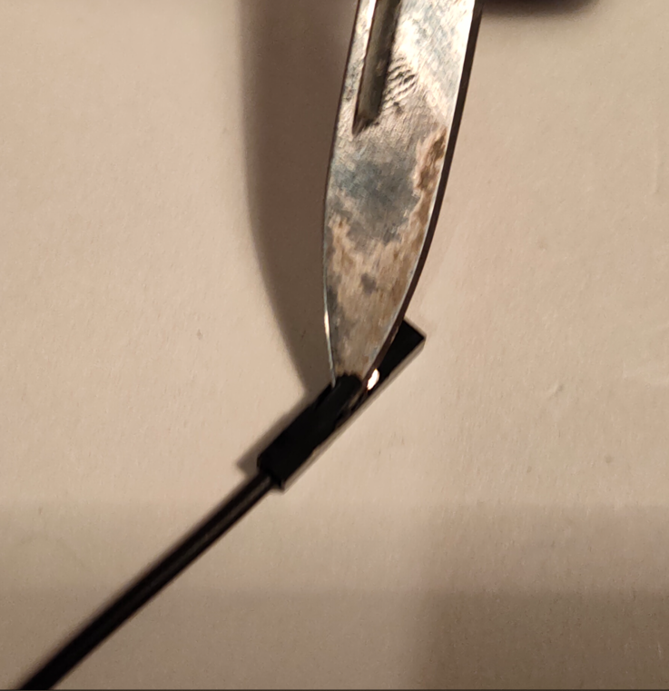
Kabot has two actuators - MG90S servos in a continous rotation version. This way, no on-board H-Bridge is needed, just one GPIO per motor and 5V power. Those servos also come with horns that can be used to attach wheels securely.
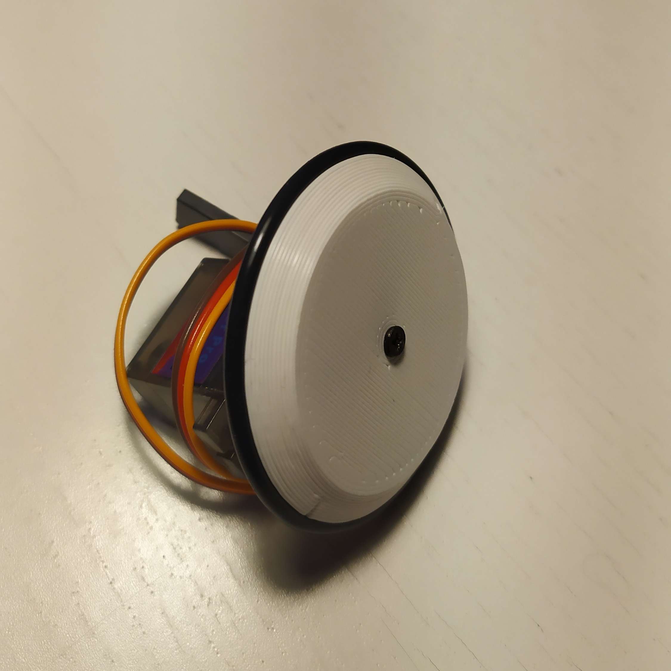
Servomotor with wheel attached.
Power:
All the electrons needed to keep the robot running are supplied via single 18650 Li-Ion cell. Charging, battery protection, and switching on and off is provided via IPS5306 - chinesium powerbank IC. Power for the charger is supplied via USB-C connector. This converter provides 5V for the servos and expansion port, and LDO provides 3.3V for the SoC and expansion port.
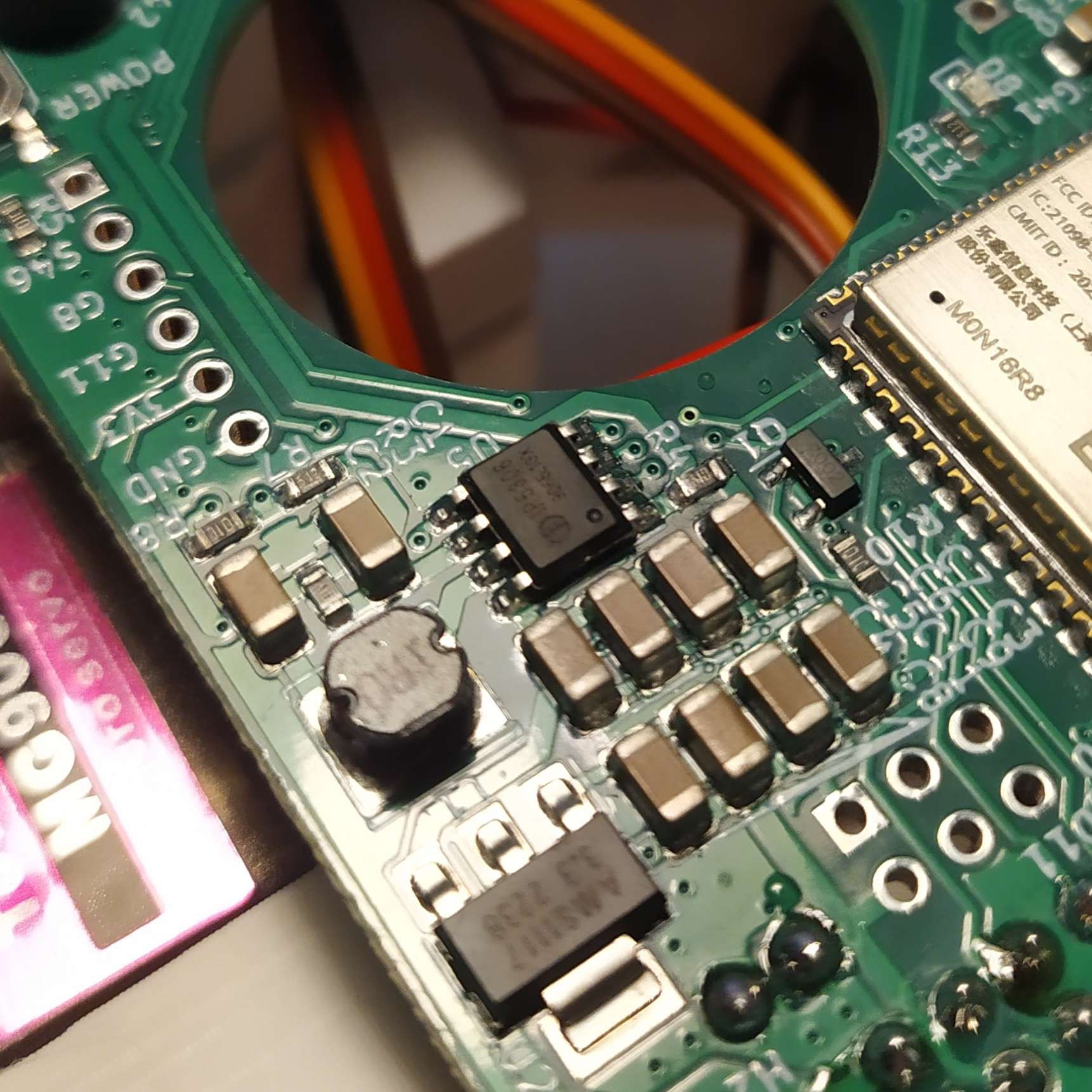
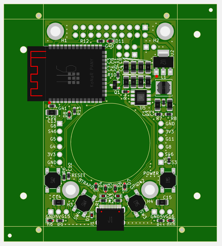
Power section of main pcb.
Brain:
The main board is based around ESP32-S3 chip, sporting 16MB of flash and 8MB of RAM. Why ESP32-S3 instead of base ESP32? S3 has built-in USB peripheral, that hosts USB-JTAG and USB-CDC out of the box, so flashing, GDB and Serial.println() works without any external hardware. Furthermore, S3 is a little beefier, and has reconfigurable GPIO matrix, which will ease development of add-on boards. Most of the communication and other internal peripherals can be configured to use any pin of the package.
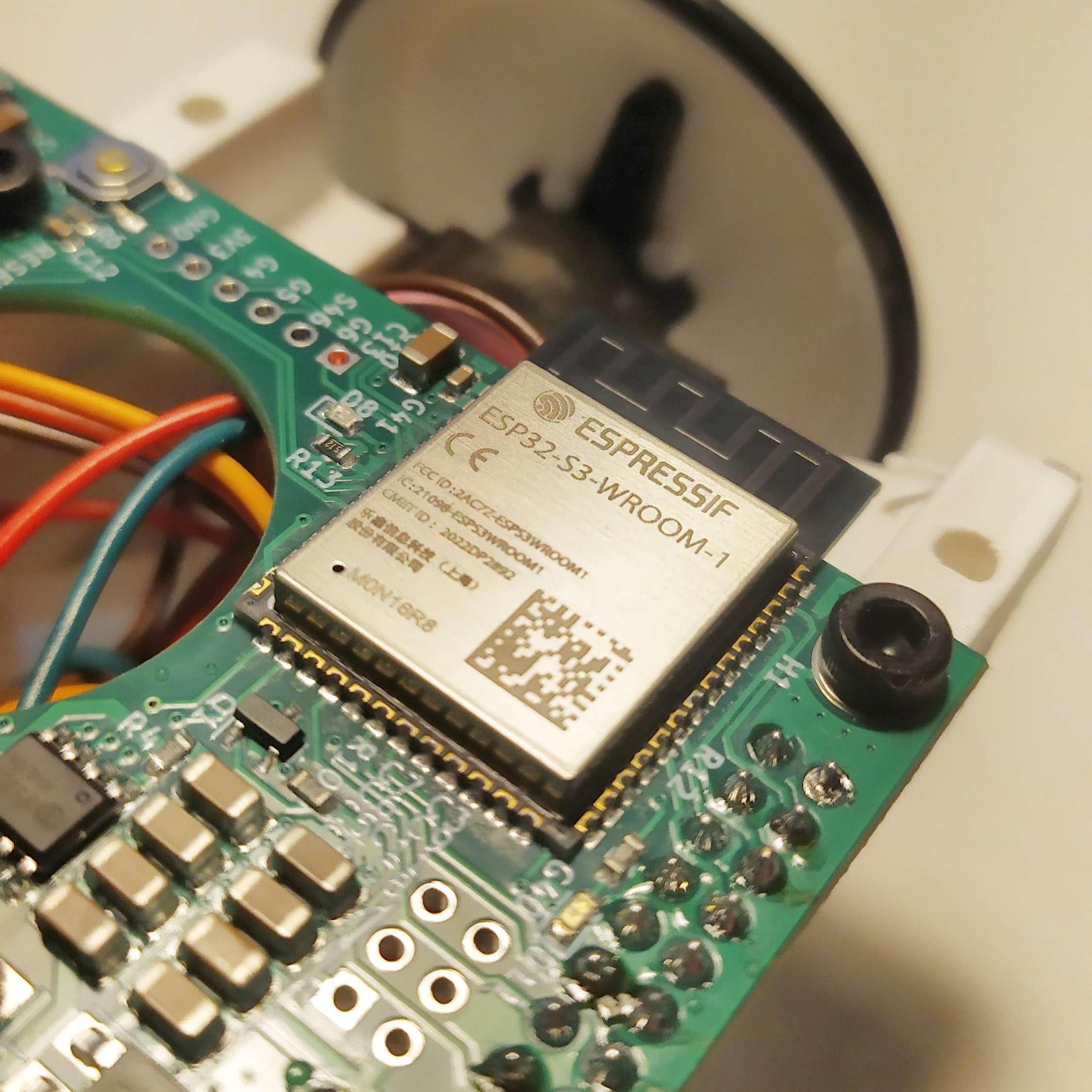
Main SoC
Software
Firmware
A framework with first-class micro-ROS support was needed. For the ESP32 family, there are really three options: vanilla ESP-IDF, arduino/platformio and Zephyr OS. Zephyr was ruled out because of the initial cost of setting up, and ESP32-S3 core support might be flakey due to the small community around this chip family across all three. ESP-IDF was also ruled out due to lack of knowledge of the framework,...
Read more »
 Petoi
Petoi
 Rodolfo
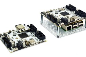
 Husarion
 Jack Qiao