Close
0%
0%

Virtual Pipe Organ

A modern twist on a classic musical instrument: the Virtual MIDI pipe organ

Similar projects worth following
Based on the success of my pipe organ pedalboard MIDI conversion (https://hackaday.io/project/4741-organ-pedalboard-midi-conversion), we've decided to take on building a complete virtual pipe organ to be used with the amazing Hauptwerk software. For this project I'll be using a Teensy 3.2 micro instead of an Arduino Uno as it makes MIDI much easier & is a lot more powerful.We'll be using some salvaged pipe organ parts (pedalboard, pistons and shoes). For manuals we've found 3 M-Audio KeyStation 61es (61-key MIDI keyboard). The organ frame & all electronics will be DIY.

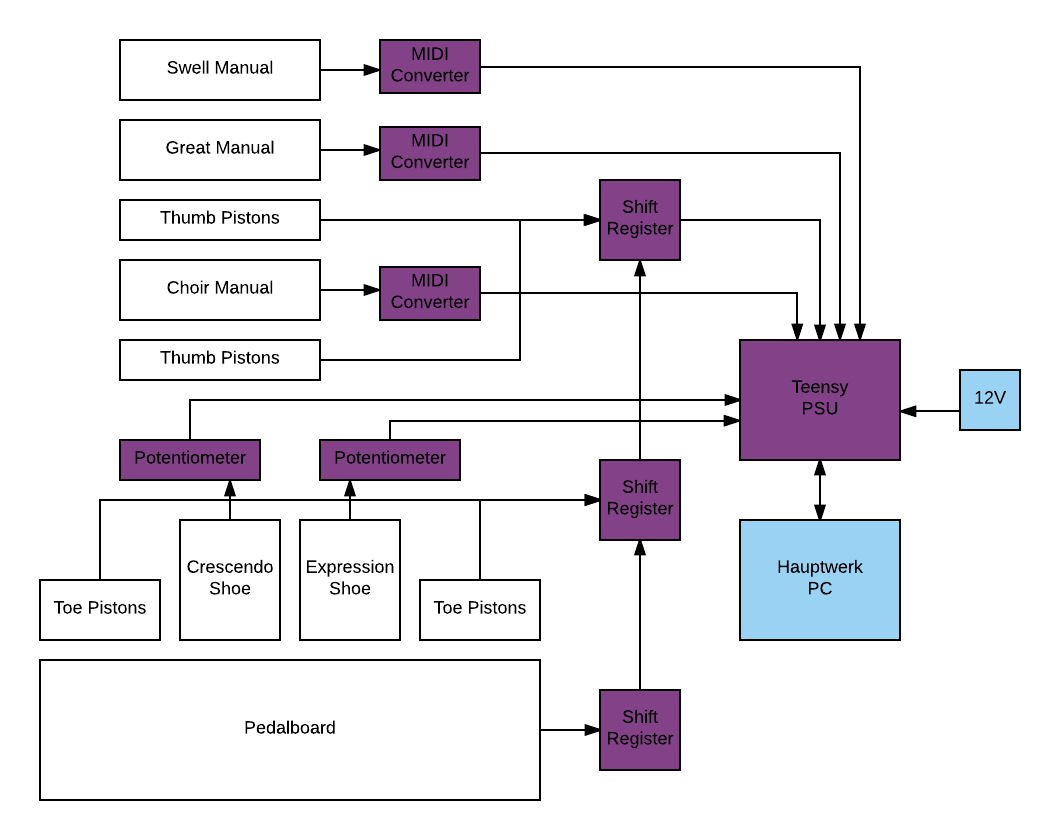
The following diagram illustrates the basic design for a VPO (Virtual Pipe Organ) serving as input for Hauptwerk software running on a PC. The white boxes are organ components, the purple boxes are custom modules I have designed.

DISCLAIMER: I have absolutely zero musical ability, but have always appreciated this great instrument. My career is in software with a hobby interest in electronics, woodwork, 3D printing etc. While none of my modules have released magic smoke over the past few years, it's quite possible there are some horrific design decisions in there. My son has a degree in Organ Technology, so I defer to him for most organ related design issues.
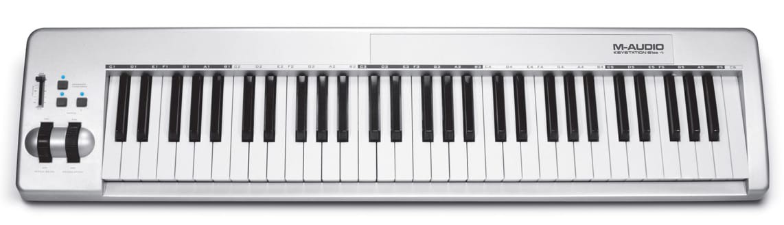
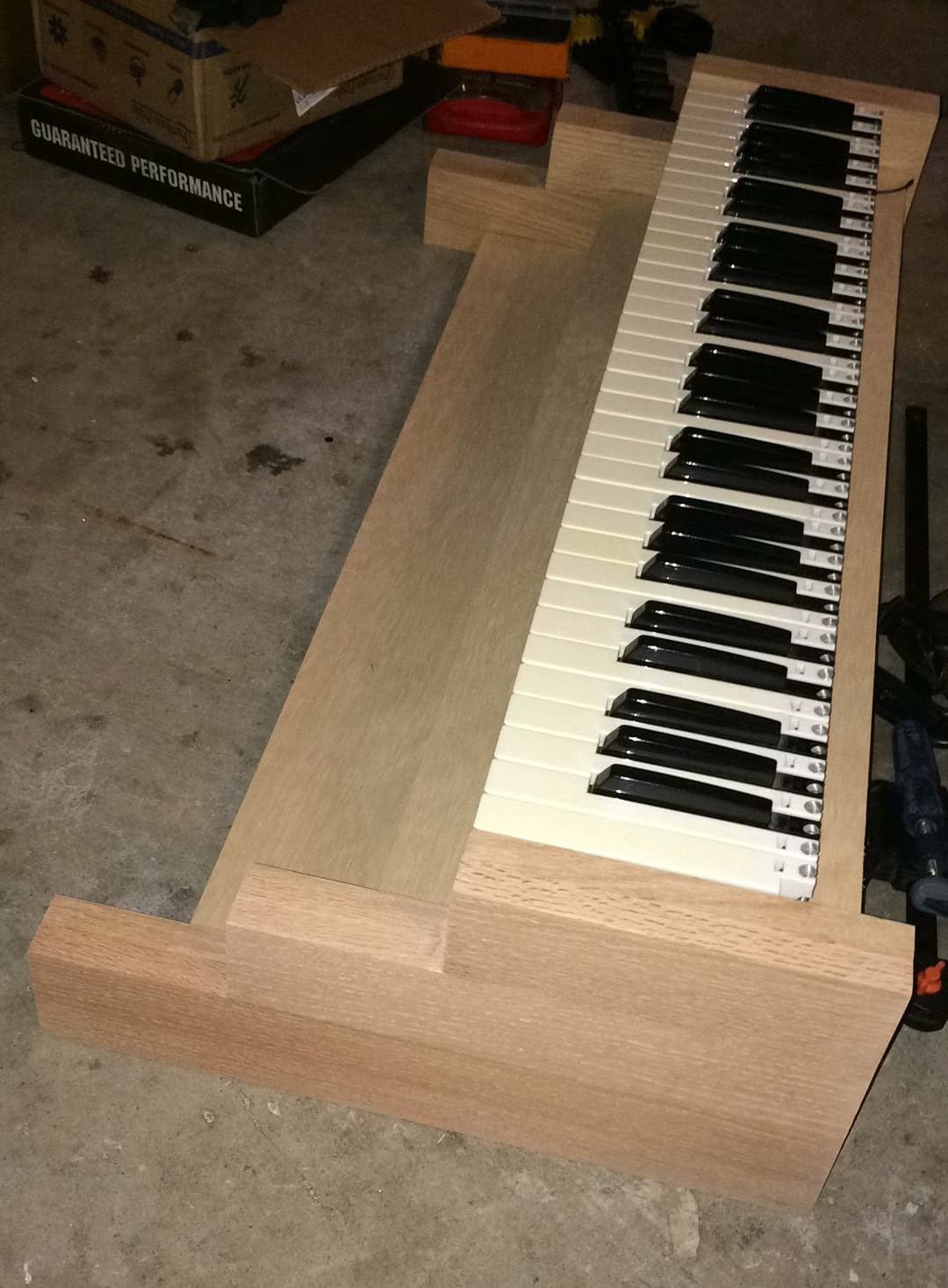
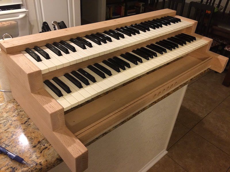
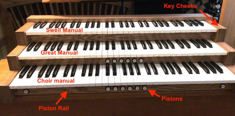
MANUALS

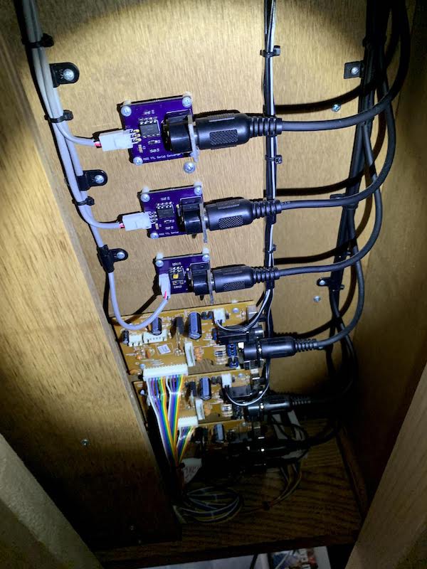
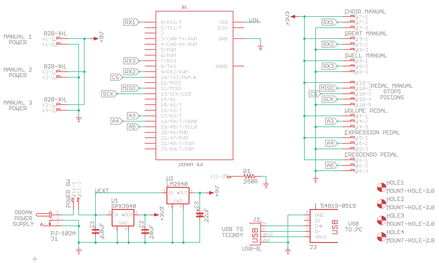
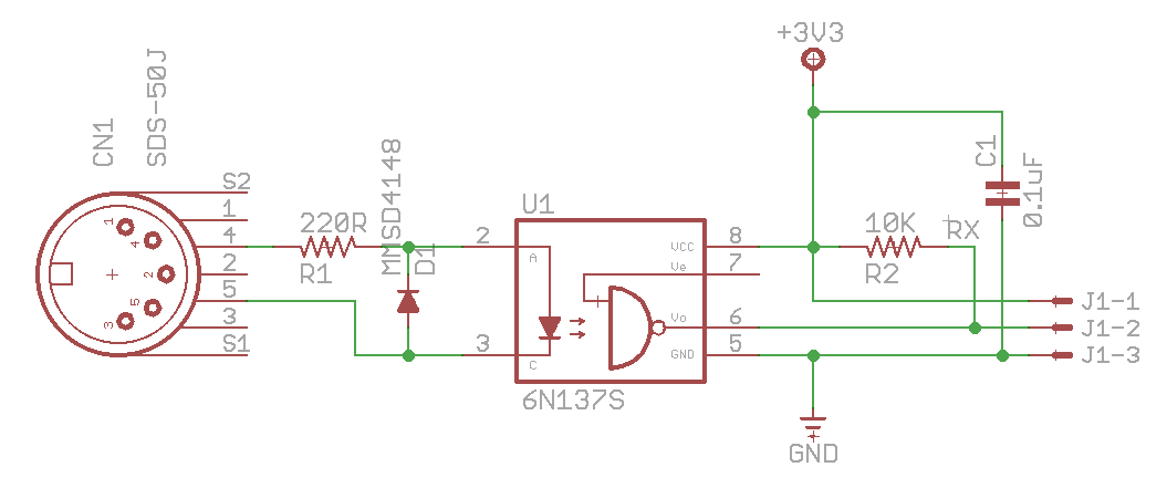
The organ will have three manuals (keyboards). The individual keyboards are powered by a 9V power supply on the main Teensy PSU module. MIDI output from the keyboard is converted into a serial protocol that the Teensy microprocessor processor can interpret, then sent to the Hauptwerk PC as MIDI Note On/Off messages on separate channels.

PEDALBOARD

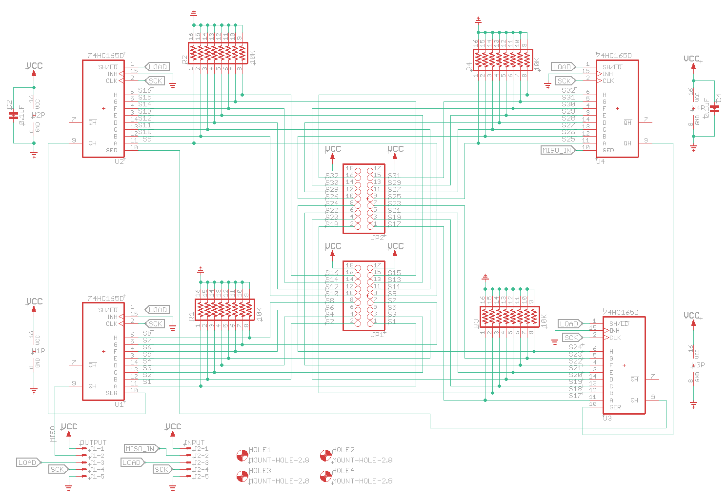
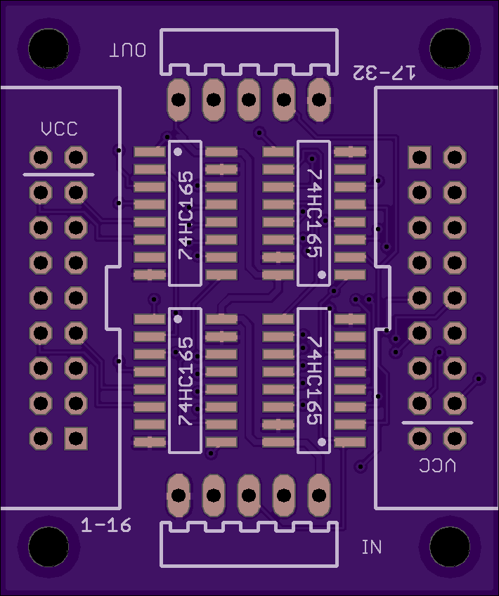
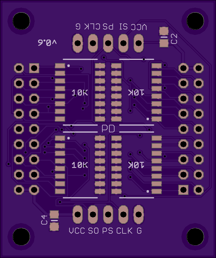
The pedalboard has 32 pedals which will need individual reed or mechanical switches. The switches are read by 74HC165 shift registers on a custom PCB. The main program running on the Teensy reads the output from the shift registers and sends MIDI Note On/Off messages to the PC.

THUMB & TOE PISTONS

The pistons are just push-to-make switches and function exactly the same as the pedalboard. These switches are also read using the same custom shift register PCB daisy chained together. The push events are sent as MIDI Program Change messages to the PC.
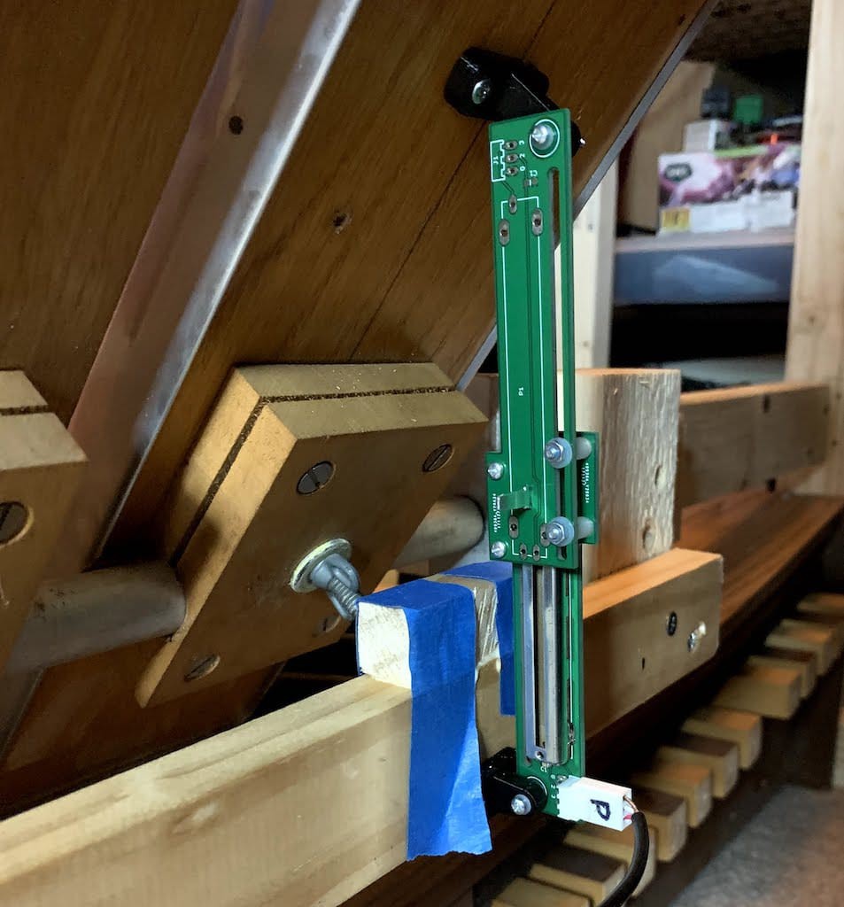
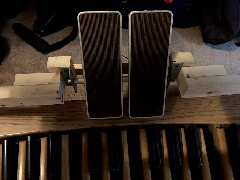
SHOES

The expression & crescendo shoes' position will be read using a linear potentiometer, also on a custom PCB, by the Teensy. The position of each pedal is read directly by the Teensy as an analog value and sent as a MIDI Control Change message to the PC.

Digikey BOM

The required components for each module can be ordered from Digikey via the following BOM (Bill Of Materials) links. Note that you will have to multiply the number of components with the number of modules you are building:

Power Supply Module: https://www.digikey.com/BOM/Create/CreateSharedBom?bomId=8237173

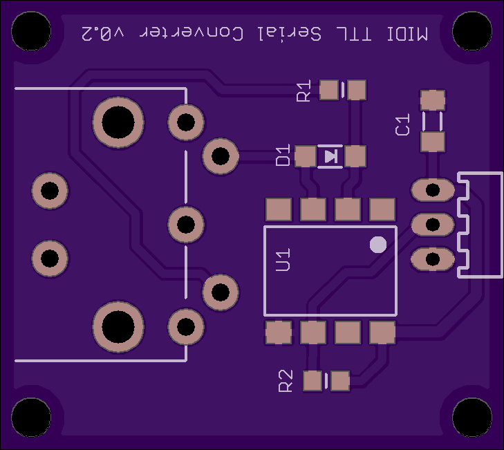
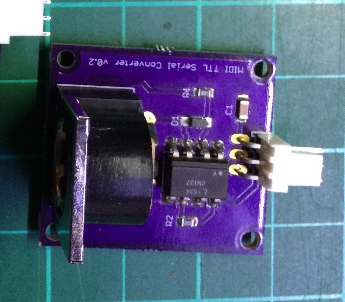
MIDI Converter Module: https://www.digikey.com/BOM/Create/CreateSharedBom?bomId=8237128

Shift Register Module: https://www.digikey.com/BOM/Create/CreateSharedBom?bomId=8237172

Pedal Module:  https://www.digikey.com/BOM/Create/CreateSharedBom?bomId=8237109
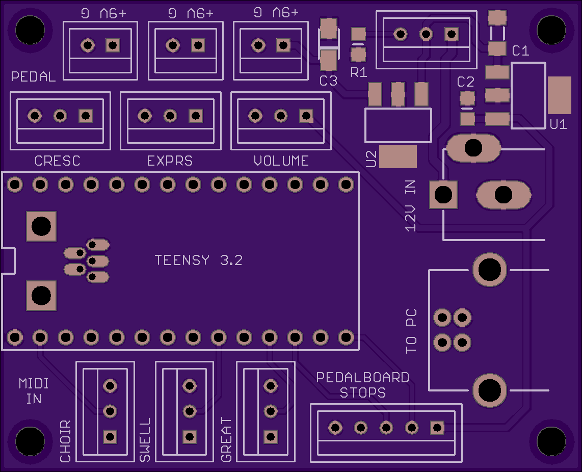
OSHPark PCB

The Eagle CAD design files are available from the linked GitHub repository in the projects links. Copies of the circuit boards can be ordered from OSHpark.com with the following links:

Power Supply Module: https://oshpark.com/shared_projects/6LYM4OFl

MIDI Converter Module: https://oshpark.com/shared_projects/HvD6Wp0o

Shift Register Module: https://oshpark.com/shared_projects/GM5weTyM

Pedal Module:  https://oshpark.com/shared_projects/FGOvTVa1

PROJECT STATUS

Main power supply module
Complete. Needs to be updated to current version
MIDI converter module
Complete & functional
Shift register module
Complete & functional
Potentiometer module
Currently testing
Organ manuals console
Complete. Need to add power switch & LED
Pedalboard conversion to MIDI
Complete. Project log to be done.
Expression & Crescendo pedals conversion
Complete & functional. Will be remade with a 3D printed design.
Toe pistons conversion
To be done
Organ stand/console
Temporary stand in use. Final steel design to be done.

IMG_4831.JPG

Shift Register & MIDI Merge modules built up

JPEG Image - 722.31 kB - 12/03/2020 at 20:22

Preview
Download

agoconsole.pdf

American Guild of Organists Standard Console Specifications

Adobe Portable Document Format - 98.73 kB - 05/03/2020 at 17:17

Preview
Download

  • 3 × M-Audio KeyStation 61es MIDI Keyboard
  • 1 × Salvaged AGO standard pedalboard
  • 3 × Salvaged thumb piston rails
  • 1 × Salvaged foot pedals, AKA shoes
  • 3 × Salvaged toe pistons

View all 9 components

  • Expression & Crescendo pedals

    Johan Cronje06/20/2020 at 17:03 0 comments

    Recently got the expression & crescendo pedals installed. The pedals were salvaged from an old organ and tension is adjusted with a wing nut - very crude but effective.

    The pedals use a 10k ohm long travel sliding potentiometer to register the pedal position. I designed a dual-purpose PCB which mounts the potentiometer and also attaches to the slider. I made 3D printed brackets in Fusion360 to mount the potentiometer. I will have to change to a shorter travel potentiometer, are these were hard to position and will be vulnerable to damage. The design will be changed to use a 3D printed enclosure for added durability. For now it serves the purpose. The taped wood block is a temporary pedal travel limiter - something else to consider for version 2.

    And here are the pedals installed somewhat temporarily positioned according to the AGO console specifications. This will be a useful template when we get around to building the final console. Have yet to decide whether it'll be a wooden or (more likely) sliding/adjustable square steel tubing so it can be disassembled easily.

    The Hauptwerk software detected the pedals immediately and just worked, which meant I got the Teensy software right the first time - that doesn't happen very often! 

  • The Manuals

    Johan Cronje05/01/2020 at 21:52 0 comments

    Building the manual console was a project on its own! The plan was to build a 3 manual console, so Choir, Great and Swell manuals, from lowest to highest. All dimensions for the console are based on the American Guild of Organists Standard Console Specifications. A PDF document describing these standards is available from the file list on the main project page.

    We scoured Craigslist for months to find three M-Audio KeyStation 61es (61-key MIDI) keyboards. These are pretty cost effective, but in hindsight noisy and not great quality. May be worth spending more to get quality keyboards.

    Unfortunately, I lost all the pictures I took while adapting the keyboards to fit in the console. I removed the main key section and the PCB from the case. The case and controls on the left are not used. The keys were mounted directly to the top of shelves in the console (detailed below) and the PCBs mounted on the bottom of the shelves. 9V power is supplied directly to each keyboard from the main Power Supply module.

    For the console sides (or key cheeks) I used 3/4" white oak planks that I got from Home Depot. Armed with rusty high school woodshop skills and a hacked together table saw using an old Skil saw, construction commenced. I cut and laminated the oak planks together to get a more substantial key cheeks. I used 3/8" plywood for the shelves the keyboards rest on. I also cut and glued some more oak strips for the piston rails between the keyboards. All limbs remained intact, I'm happy to report!

    The CAD file for the key cheeks are available in my GitHub repo at https://github.com/Nkawu/Virtual_Pipe_Organ/tree/master/cad. The DXF file is a pretty common format and the F3D file is for Fusion 360.

    About halfway through, testing the keyboard fit.

    A little further along the holes for the thumb pistons can be seen on the lowest piston rail.

    The original keyboard PCBs, MIDI Converters, Main Control Power Supply and one Shift Register module were mounted below the top shelf. I had to extend the cable between the keyboard and PCB. Just made new ones using ribbon cable. The black DIN cables go from the keyboard PCB to the MIDI Converter modules for each keyboard.

    and completed! The thumb piston buttons were appropriated from a salvaged piston rail

    As a note, these specific keyboards have a long extension on the front edge of the keys that block the thumb pistons and contact the keyboard below. I used a mini saw blade on a Dremel to cut along a taped on straight edge to trim all the keys as can be seen above.

  • Main Control & Power Module

    Johan Cronje05/01/2020 at 21:09 0 comments

    This is the "main" module for the organ and serves several purposes:

    • Houses the awesome Teensy 3.2 micro-controller (https://www.pjrc.com/store/teensy32.html) that handles all the processing & communication for the organ
    • With external power provided by any 12V power brick, converts and supplies 3.3V to the Teensy and all switches, as well as 9V to the 3 MIDI keyboards.
    • Allows for a small power indicator LED to be mounted in the console somewhere
    • Allows for an external switch to be mounted to turn off power to the organ
    • Central hub to connect all external modules to the Teensy
    • Adds a durable USB Type B jack to connect to the Hauptwerk PC, linked to the Teensy via a mini-USB jumper cable connected to an additional mini-USB connector on the module. This allows for either a USB Type B or mini-USB cable to be used to connect to the the PC.

    Three hardware serial ports on the Teensy are used to read the serialized MIDI input from the choir, great & swell manuals on pin 0 (RX1, 9 (RX2) & 7 (RX3).

    The daisy-chained shift register modules are read via the SPI, pins 10 (CS), 12 (DIN) & 13 (SCK)

    The great & swell expression pedals plus the crescendo pedal are read by analog pins 17 (A3), 18 (A4) & 19 (A5)

    NOTE: Any references to VOLUME PEDAL refers to the great expression pedal,  and EXPRESSION PEDAL refers to the swell expression pedal. My son corrected my ignorant terminology!

    Also had these PCBs made at OSHpark.com. The final design:

    And the finished item (using an earlier version of the module without the power switch & indicator) mounted inside the console:

  • Shift Register Module

    Johan Cronje05/01/2020 at 20:39 0 comments

    The organ potentially has hundreds of ON/OFF switches that have to be read. For example the pedalboard alone will have 32 pedals with reed or mechanical wiper switches. If you decided to add (thumb) pistons, toe studs/pistons or stop/draw knobs, you may have many more which would require lots and lots of wiring. The way to address this, is to use shift registers that read parallel inputs but transmit them serially, in effect 8 inputs to a single output.

    My approach was to make a Shift Register module PCB that contains 4 shift register chips, allowing 32 inputs to be sent via 1 output. In addition, not only can the shift register chips be daisy chained, but the modules can also be daisy chained. This allows for much simplified wiring.

    On each module 32 individual switches can be read by four daisy chained 74HC165 shift registers. I went with the 74HC165 instead of the CD4021 I used previously as they handle the Teensy's 3.3V better.

    As I have switches in 3 locations, I designed each module to have 32 inputs. That way a single module can handle the pedalboard, another the thumb pistons, drawstops, etc. I once again had these made at OSHpark.com.

    The final PCB design:


    And the finished item mounted on the pedalboard:

  • A very belated update

    Johan Cronje05/01/2020 at 17:06 0 comments

    My apologies for the lack of updates for so long. As my son was going away to college and needed to take the organ with him, it was a huge rush to get the instrument functional,  Good news is it has been working flawlessly for several years. He is now back home due to COVID-19 with the organ, so I'm finally able to provide more detail about the construction.

    Thanks for your patience, look out for updates over the next few weeks. Also thanks to COVID-19, I got laid off this week, so will definitely have time to complete this.

  • MIDI Converter

    Johan Cronje12/22/2016 at 23:05 0 comments

    The following schematic converts MIDI input messages from the M-Audio Keystation keyboards to something the Teensy can understand. There are many examples around how to do this, so no need to reinvent the wheel. I selected a schematic using the highly recommended 6N137 Logic Output Optoisolator chip used by many commercial products:

    As I have 3 MIDI streams that I have to convert, I decided to create single input PCBs (as opposed to a single PCB with 3 MIDI inputs). The only reason I decided to do this is that OSHpark.com where I get my PCBs made, has a minimum order quantity of three.

    The final PCB design:

    And the finished item:


  • The Design

    Johan Cronje12/21/2016 at 23:46 0 comments

    This is the basic design for the VPO (Virtual Pipe Organ). The white boxes are organ components, the purple boxes are custom modules I have designed.

    MANUALS

    The organ will have three manuals (keyboards). While the M-Audio Keystation 61es devices have a USB interface, the issue I found while testing is that when multiple keyboards are connected the order won't always be the same. I therefore decided to use the MIDI output port with a custom PCB to convert the MIDI output stream to something the Teensy can understand. The downside to doing this is that the keyboard receives power via USB, which means it now needs a separate power supply.

    Another advantage of using the Teensy 3.2 here is that is has three hardware serial ports, one for each manual. This means we can read multiple MIDI input streams and simultaneously output a USB MIDI stream to the connected PC.

    The main PCB will house the Teensy 3.2 as well as providing 3.3V to the auxiliary circuits and 9V to power the three manuals.

    PEDALBOARD

    Most of the work for the pedalboard was done in the previous project. I realized the Arduino Uno shield method I was using was very limiting, therefore decided to use the amazing Teensy 3.2 for this project.

    The pedalboard will have 32 pedals with reed or mechanical wiper switches. The switches are read by four daisy chained 74HC165 shift registers on a custom PCB. I went with the 74HC165 instead of the CD4021 I used previously as they handle 3.3V better.

    TOE & THUMB PISTONS

    The pistons are just push-to-make switches and function exactly the same as the pedalboard. These switches are also read using the same custom shift register PCB daisy chained together.

    SHOES

    The expression & crescendo shoes' position will be read using a linear potentiometer, also on a custom PCB, by the Teensy.

View all 7 project logs

Enjoy this project?

Share

Discussions

Henry Podgorny wrote 12/03/2020 at 02:42 point

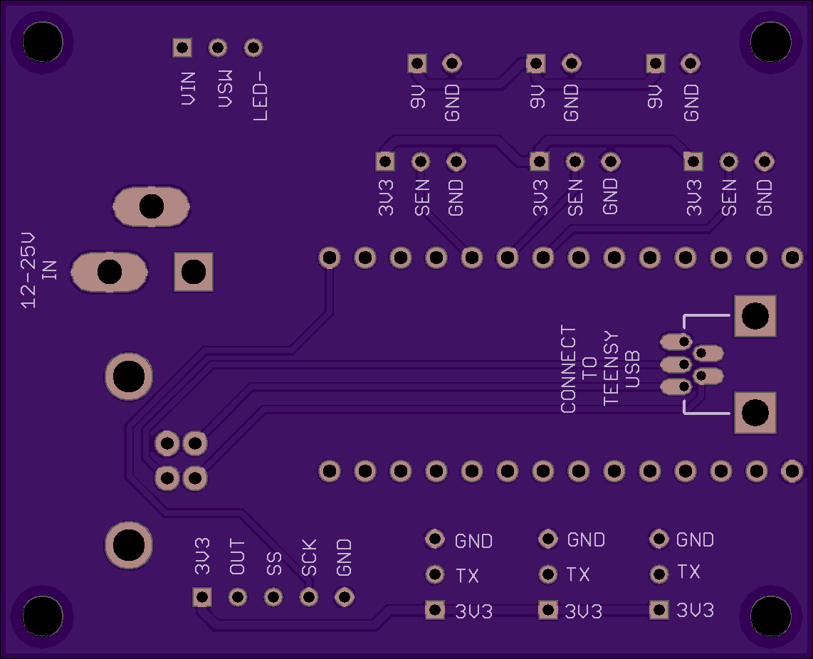
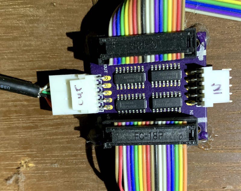
Great project and I would like to implement it for the conversion of my Conn organ. Is it possible that you could show pictures of the (Power and Shift)  circuit boards back  side  populated with the appropriate electrical components. Thank you,

  Are you sure? yes | no

Johan Cronje wrote 12/03/2020 at 20:28 point

Hi Henry. I added the only image I had of the modules to the "Files" tab at the top. I'll try to find one of the power module. As far as I recall the only component mounted to the bottom of the power supply board is a mini USB connector.

  Are you sure? yes | no

Similar Projects

Does this project spark your interest?

Become a member to follow this project and never miss any updates