 Deepak Khatri
Would you believe a sensor exists with BOM cost as low as $1 which can be made on a breadboard and can record biopotential signals with such accuracy that you can create sophisticated Human-Computer Interface (HCI) devices with ease?
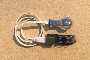
The GIF animation below shows one such home made sensor I developed during late 2020 which is called BioAmp EMG Pill. The project was covered by Hackaday.com as well.
It's all possible because of the years of research I had put into perfecting the BioAmp design making it the most affordable biopotential sensing solution. We at Upside Down Labs believe in open science thus everything we do at Upside Down Labs is open for all be it our Hardware, Software, or Documentation.
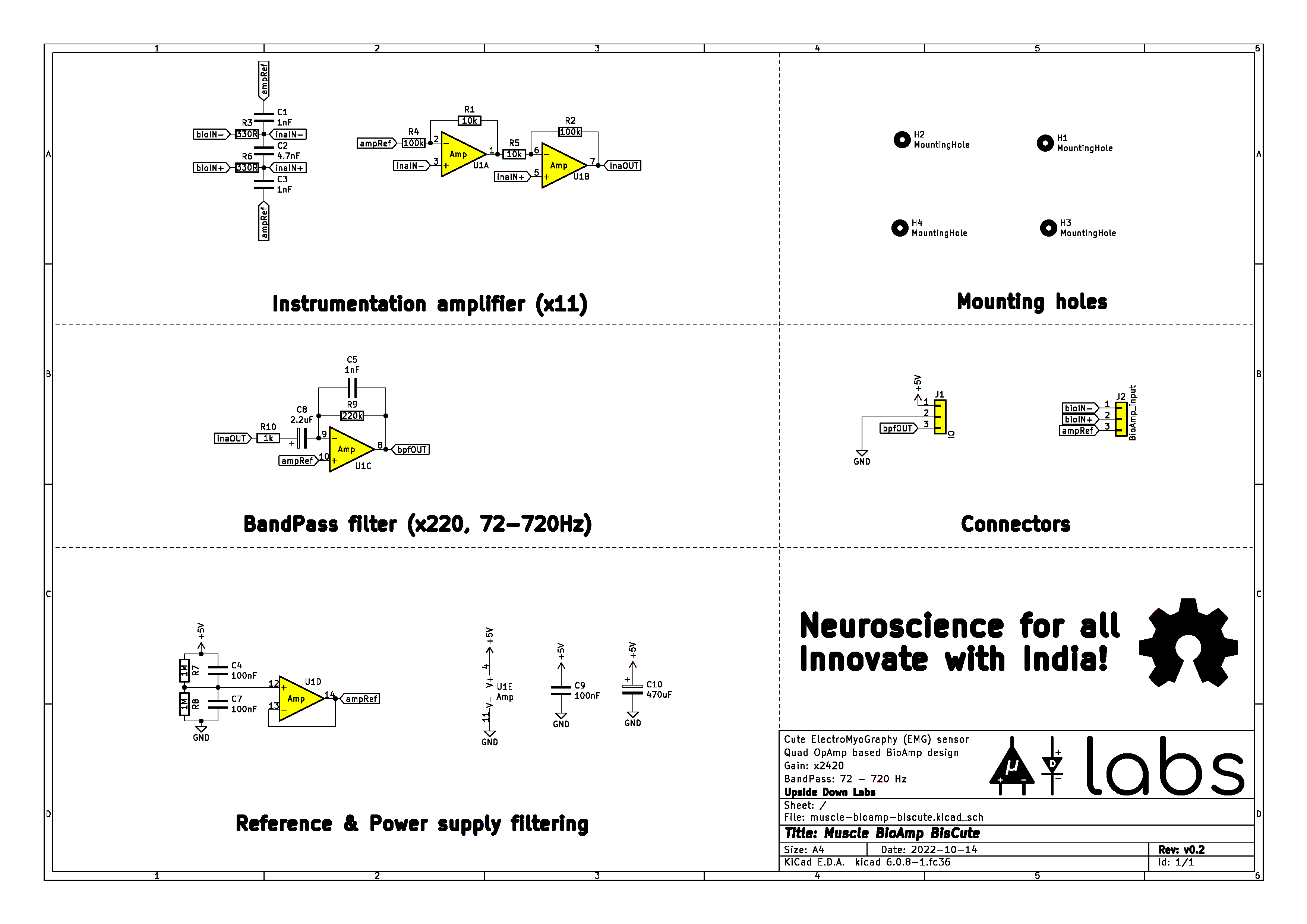
Without considering the overhead cost of setting up a lab and purchasing tools the BOM cost of making a BioAmp can be as low as $1 if you choose the parts correctly. The DIY Muscle BioAmp BisCute design is very minimalist which can easily be built on a breadboard using LM324, 1% precision resistors, ceramic disc capacitors and some electrolytic capacitors. Below is the schematic diagram of Muscle BioAmp Biscute if you are interested to replicate it on a breadboard.
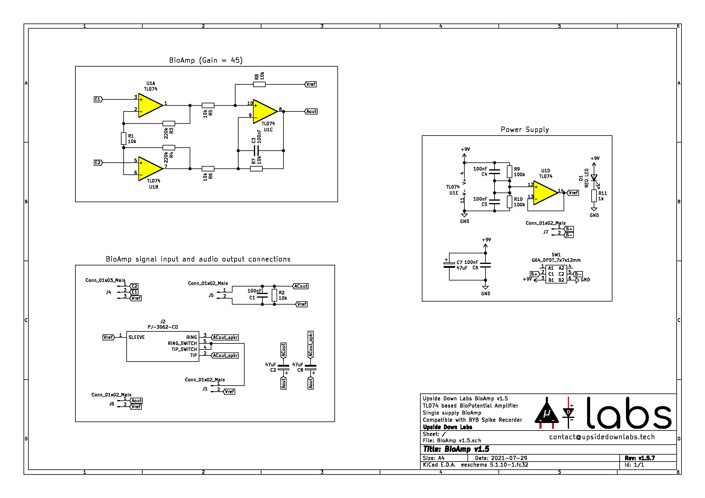
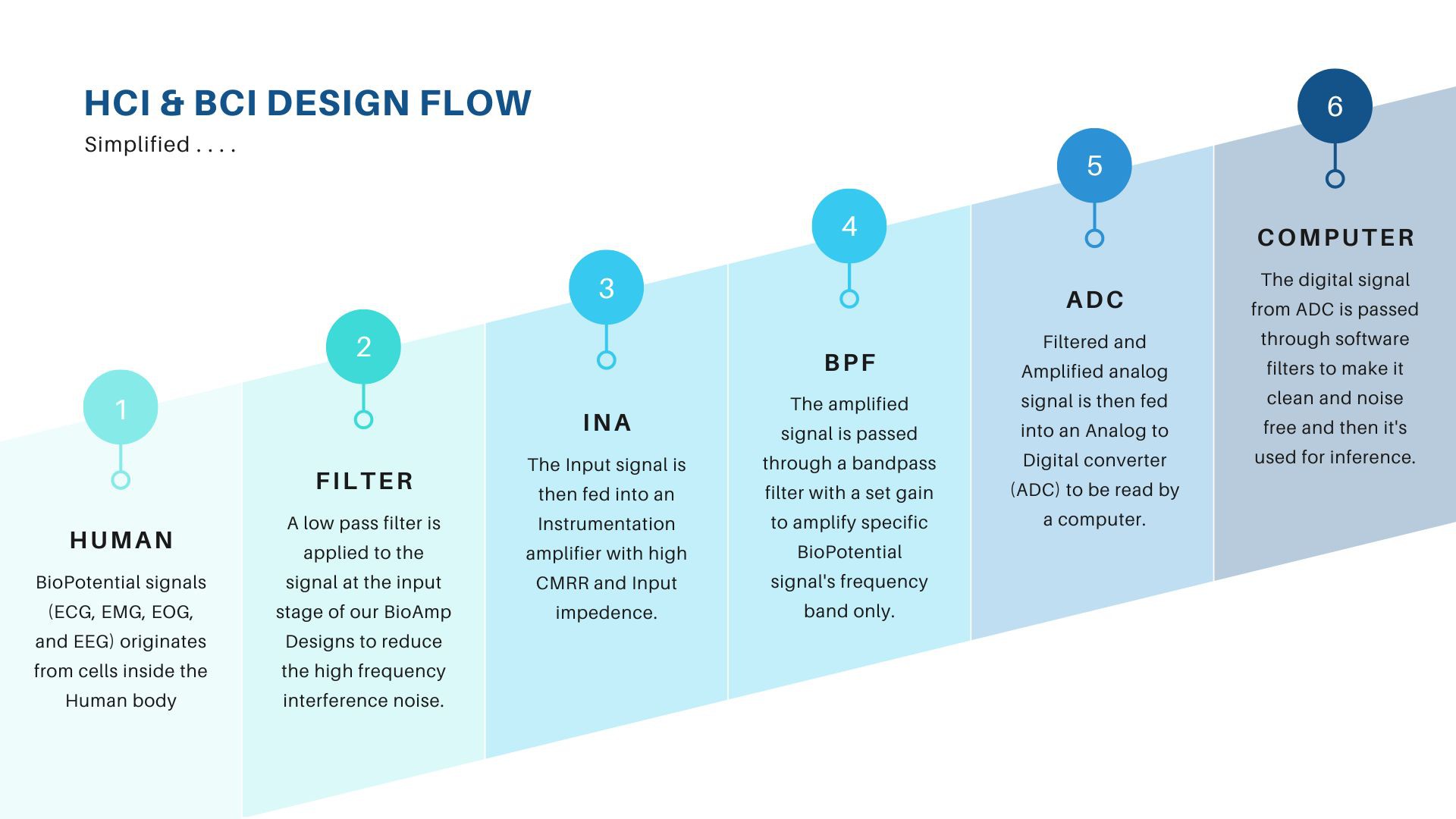
To create even simpler BioAmp for listening your EMG signals using a pair of headphones or visualizing & recording on a mobile phone/laptop using microphone input you can choose to build the BioAmp v1.5 sensor. Below is a simple BioAmp design which uses jelly bean parts like TL074 and 1% precision resistors to create a sophisticated EMG sesnor that can easily be interfaced with a mobile/laptop to create Human Control Interface (HCI) with ease. The digitized signals using microphone input (internal ADC) can be used to create game controller to play various games like chrome dino game. The BioAmp can also be used to create control interfaces to design an assistice device for people with disabilities.
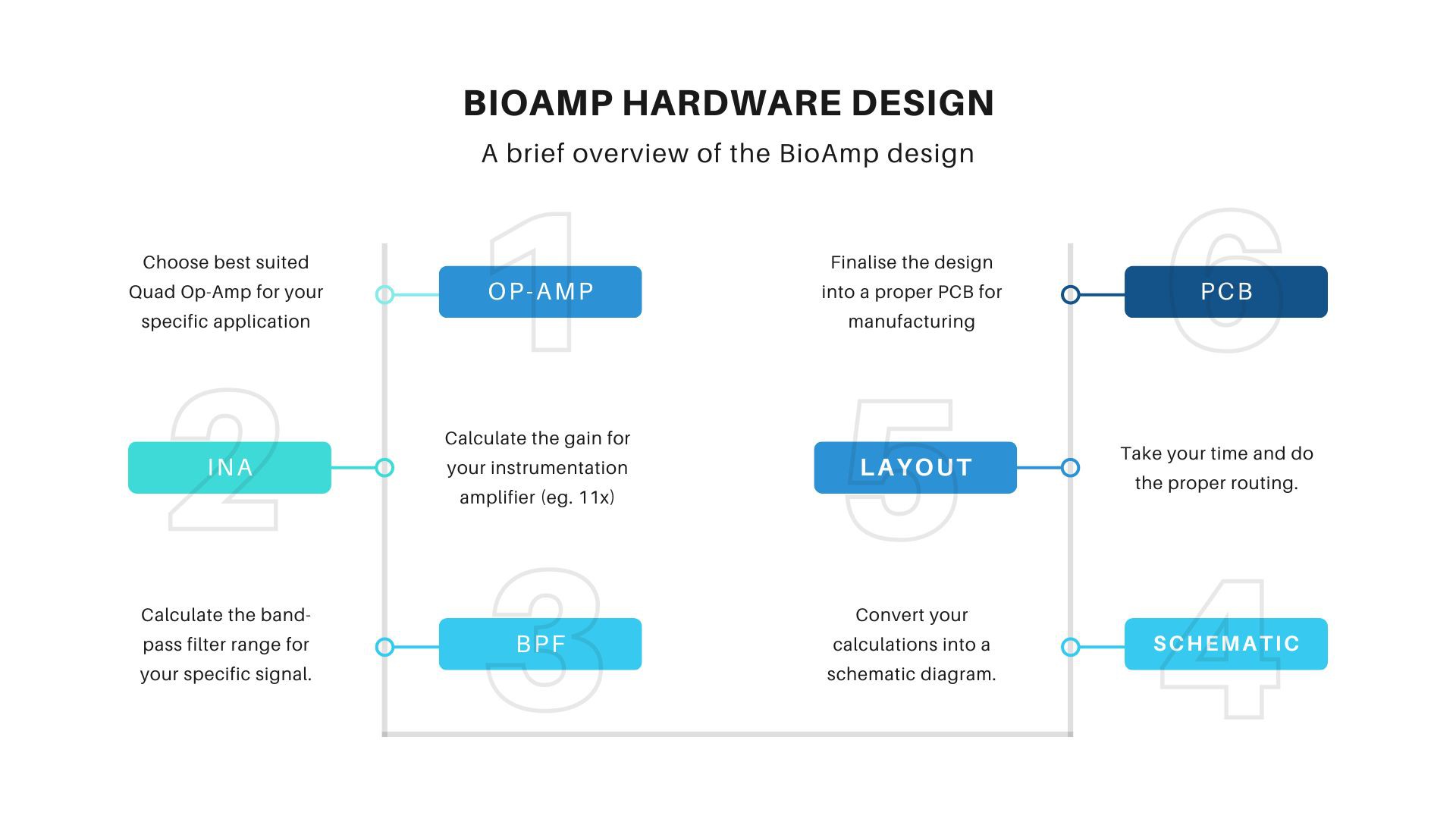
For more detail on how to design a BioAmp you can take a look at the assembly instructions in which we have gone through all the details of design a BioAmp starting at $1
 oneohm
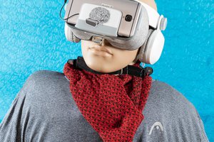
 Varun Suresh
 Abe Megahed
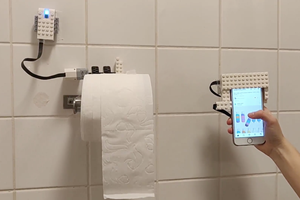
 Ilse pouwels