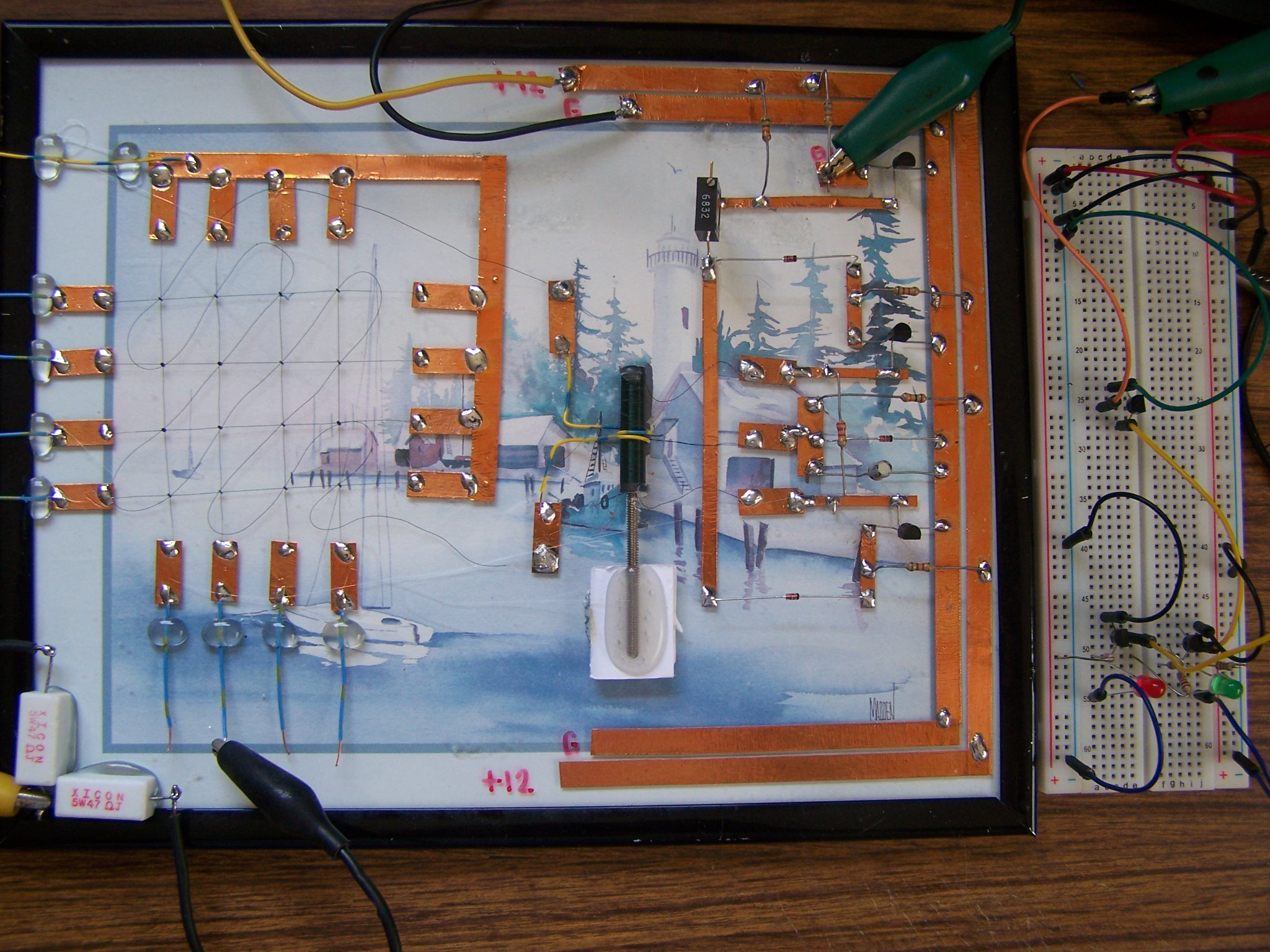
Close
0%
0%

Magnetic Core Memory The Dr Cockroach Way

My not so fancy example of Magnetic Core Memory using fairly cheap cores and free parts from my junk box.

Similar projects worth following
Back in the late 1970's I had a friend who had a stack of Magnetic Core Memory as a show piece. At the time I thought it was cool but left it at that. More recently I have seen several articles about this historic method of storing data that spanned from the late 1940's to the mid 1970's and it became a itch that just had to be scratched.

This is a very basic 16 bit Magnetic Core Memory board with a minimal but stable Read circuit just using six transistors. After viewing several project pages on MCM I decided to give it a try and see how basic I could make a working setup. Using my glass and copper tape method of construction, the circuit at the heart is the Read Sense circuit used in the Casio AL-1000 calculator from the late 1960's

This build is just a learning example. Future use will require scaling up to at least four layers for 4 bit Nibbles.

A big thanks to @Andy Geppert for letting me bounce my ideas and progress off of him.

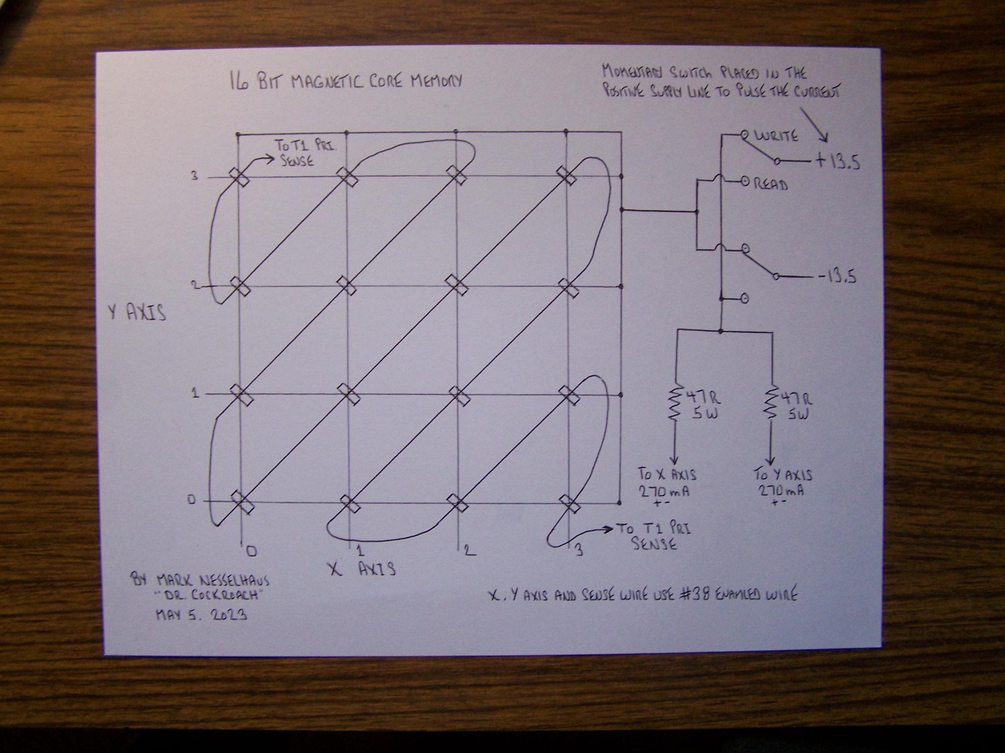
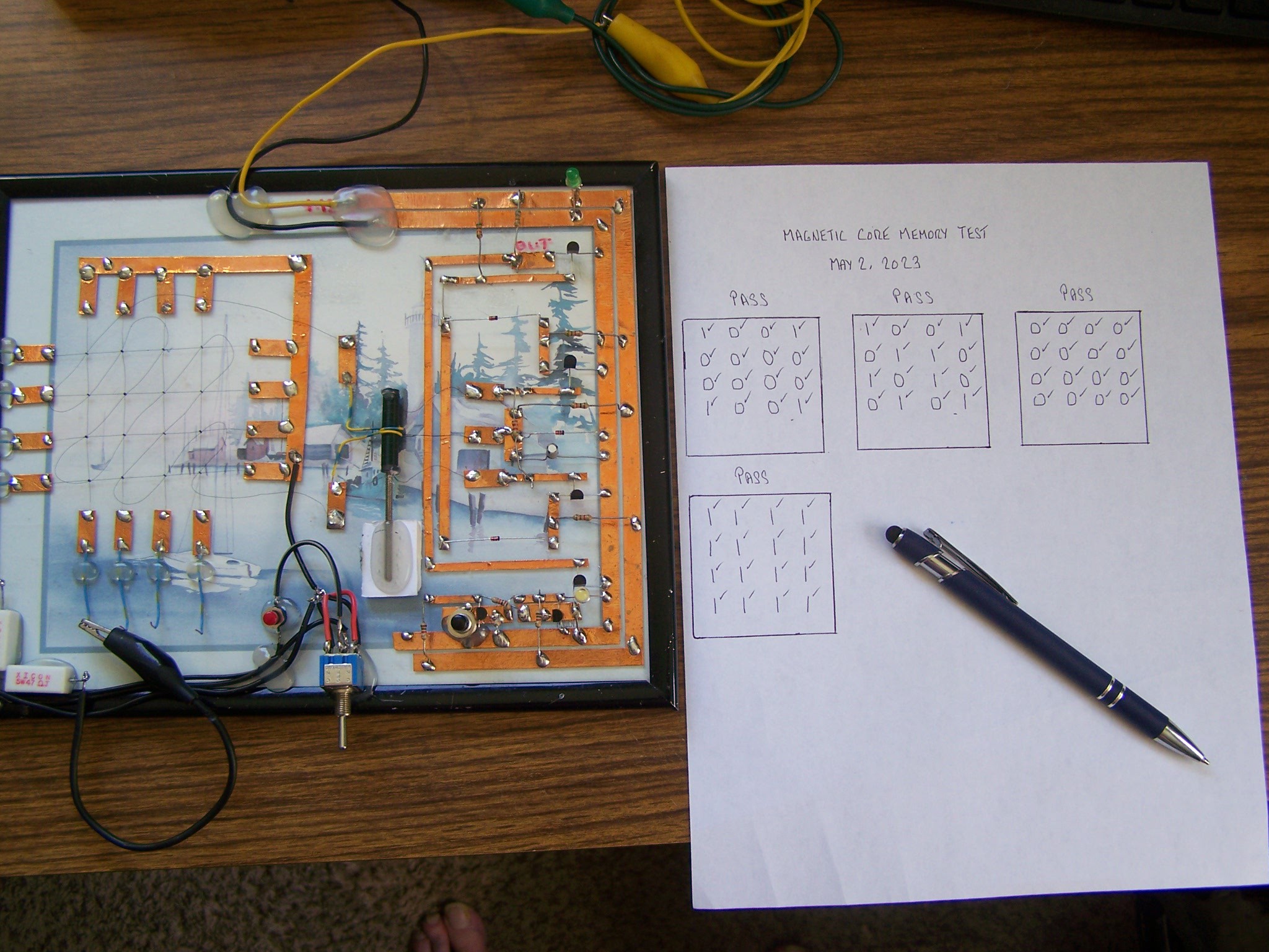
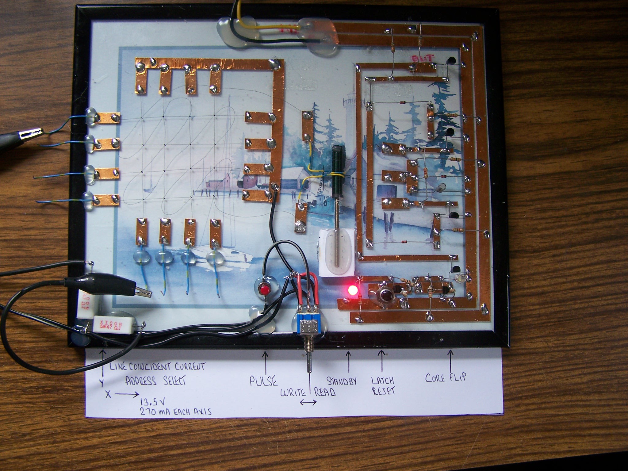
How much memory does this project have? 16 bits.

How much current does it take to flip a core? 540mA total per each core in this case.

                                                                            Or 270mA for each selected X and Y wire.

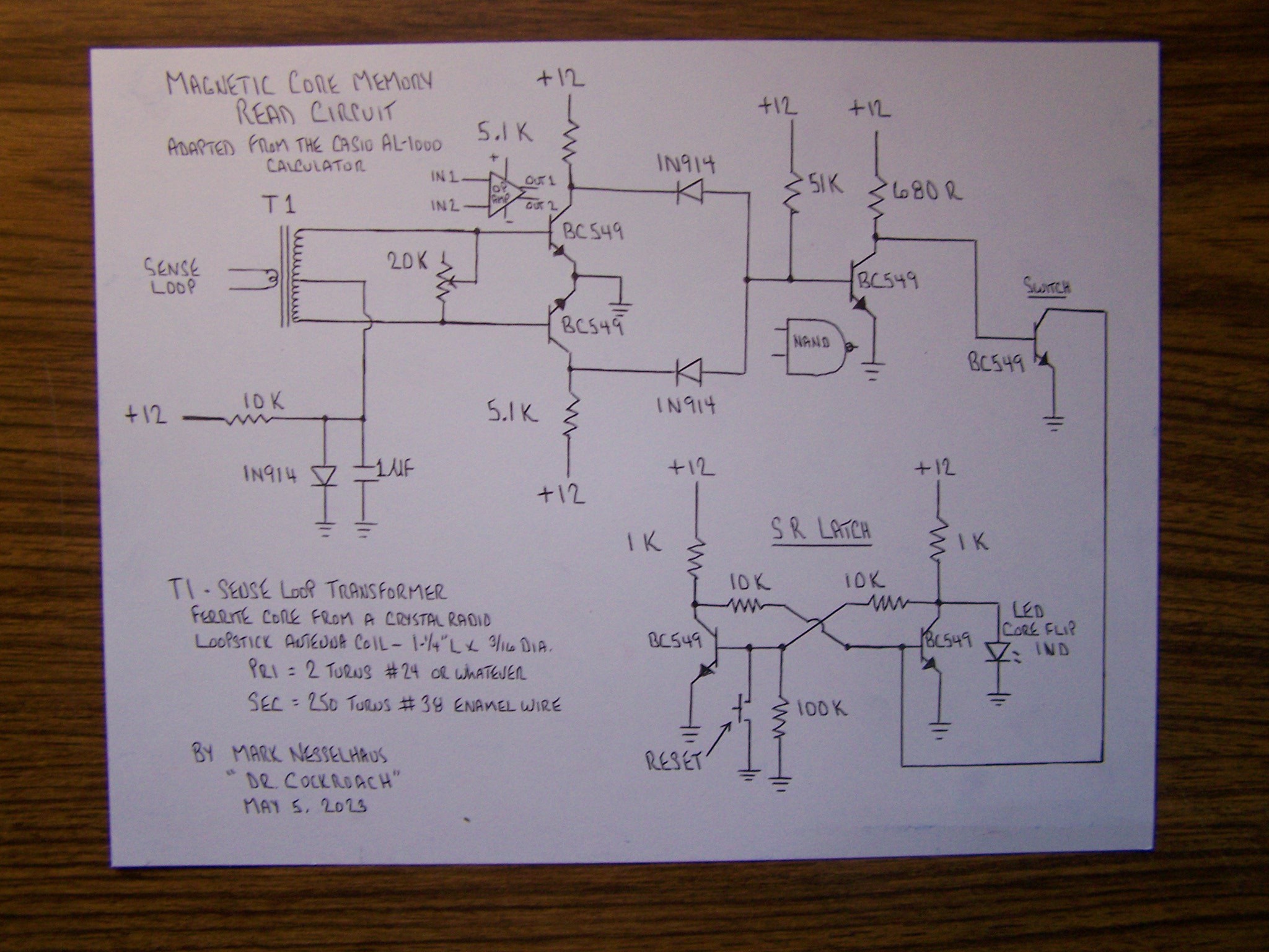
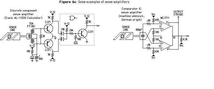
Voltage requirements? +12 Volts for the Sense and Latch circuit.

                                      +13.5 Volts for the X and Y coincident current wires

Can the X and Y current wires be addressed? Yes. A future project is to scale up more memory and include the logic required to address the writing and reading of the cores as well as a automatic Write after Read cycle to preserve the prior memory state.

Is the memory lost when power is removed? No. The cores retain their magnetic state when power is removed. Nonvolatile Memory.

What kind of copper foil is being used? Stained Glass Foiling Tape found in many hobby and craft stores. The foil takes solder quite well but the heat of soldering will weaken the adhesive on smaller pads and they will move around a little until cooled.

  • One Last Bug Solved

    Dr. Cockroach05/29/2023 at 22:32 0 comments

    May 29, 2023 - While working with this circuit I noticed that there were times that reading back a bit would be incorrect. It comes down to if I have all the power leads connected and the the power supply to the cores is turned on, then a current spike seems to get into the X and Y wires even if I have not pressed the pulse button. If I first turn on the power supply then connect the power leads, the cores read back their state correctly. I need to remember this for future builds.

  • Video Presentation

    Dr. Cockroach05/05/2023 at 23:51 0 comments

  • Magnetic Core Memory Circuit

    Dr. Cockroach05/05/2023 at 10:51 0 comments

    May 5, 2023

    This is about as basic/bare bones of a circuit that I think will work and still give solid Read results. The stringing of the core wires using number 38 enameled wire was not as much of an issue as I was fearing.

    The Sense circuit starts off with the Transformer and feeds into a very basic Differential Op Amp. The detected read pulse then triggers a Nand gate and switch that then sets the S-R Latch. This circuit is adapted from the Casio AL-1000 calculator from 1967/1968.

  • Formal Core Test Day

    Dr. Cockroach05/02/2023 at 19:57 0 comments

    May 2, 2023 -  About time I performed a formal test of the core memory. Today has been a good day. I removed the Red Led from the latch circuit as it was distracting and not really needed. I also added a Green Led as a power indicator for the Sense circuit. All the tests have passed......... So far.

  • Noise Spikes, I Jinxed Myself

    Dr. Cockroach05/01/2023 at 18:20 0 comments

    May 1, 2023 -  Seems like I jinxed myself the other day when I stated that this core memory had worked without errors for four days. I should learn to keep my mouth shut. I started seeing glitches and dropped bits for the last two days. I checked solder joints and such and thought I solved the issues but then they started up again. Just now thought that perhaps I was seeing noise spikes getting through the power supply for the transistor section of the circuit so I have added a choke of about 100mH to the power lead. I also reduced the voltage to the transistor section from 12V to 5V and everything seems to be back in good order. Going to have to cycle the cores many times to see if all is happy once again.

    Well, the glitches started up shortly after adding the choke. I took a long close look at all my solder connections and lo and behold I noticed that where two copper foils met, they were barely touching at a tiny speck of one corner and not soldered. That is now soldered and starting another round of testing. I feel good that the glitches have been solved at last.

    Four hours later and still working as it should.

  • Added the SR Latch to the main board

    Dr. Cockroach04/28/2023 at 18:44 0 comments

    April 29, 2023 -  Cleaning up some of the clip leads and moved the SR Latch to the main glass board. Now three days without any bit flip errors.

    The SR Latch is now located at the lower right with the black reset switch to the right of the red Led. The toggle switch selects between Write and Read and the red push button switch left of the toggle sends current to the selected core via the clip leads. The clear white Led at the far right indicates a flip of the selected core.

  • Dealing with the cores

    Dr. Cockroach04/27/2023 at 11:56 2 comments

    April 27, 2023 - The cores that I bought via Ebay came from Bulgaria and I have no idea of the core material specs. Andy Geppert told me what he used as far as a voltage and current with his Core64 project so I started with that but with these cores I was not getting consistent results. With a lot of flip cycles, I am now Writing and Reading at 13.5 Volts at 270 mA in the X and Y matrix wires. The two 47 Ohm resistors actually measure out as 50 Ohms. So far today I have not had a mis-read and feeling that I am on the right track as the cores held there state overnight.

  • The Circuit at the Heart

    Dr. Cockroach04/25/2023 at 22:03 0 comments

    The very basic Sense Read circuit is directly from the Casio AL-1000 calculator. The only issue I had was the Sense Transformer as I could not find any information on the TDK part called out so I just took a wild guess and wound my own transformer. I also used NPN transistors and reversed the voltage polarity but other wise the same functional circuit. There are quite a few good articles on the internet to help learn how Magnetic Core Memory works and what is required. This is the Read portion of a three wire system where the memory Read is destructive and once a bit is read as a 1, the core flips to the reverse magnetic orientation which requires the bit to be rewriten to its prior state. In 1965 IBM patented a 4 wire non-destructive system but the timing is much too complex for this current experiment.

    The voltage on the X and Y address wires is currently about 13.5 Volts @ 270 mA per active wire using a pair of 47 Ohm 5 Watt resistors, one for each axis.

    I also used BC-549 NPN transistors and reversed the voltage polarity. The NAND gate circuit can be what ever you want to use.

    The experimental board on the right is a basic transistor switch and a SR-Latch.

View all 8 project logs

Enjoy this project?

Share

Discussions

Kuba Sunderland-Ober wrote 05/30/2023 at 13:42 point

Great idea and a wonderfully quirky execution. That layout method is quite charming. A good inspiration!

  Are you sure? yes | no

Dr. Cockroach wrote 05/30/2023 at 13:52 point

Thanks, I tend to do things a bit differently ;-)

  Are you sure? yes | no

Joe Watson wrote 05/24/2023 at 20:48 point

Nice to see someone playing with magnetic cores. You might find some elements of interest in an article on one of my pages where many years ago I examined and was amazed by the design for an IBM 1620 core memory. The designers were obviously driven to minimize the number of driver transistors in their hardware design. It took me a while to figure out what was going on, but found it to be quite slick. Here is where you can find it: https://www.angelfire.com/oh3/ebjoew/IBM_1620_Core_Memory.html

  Are you sure? yes | no

Dr. Cockroach wrote 05/24/2023 at 21:09 point

Thanks, I found that link very interesting so I will take a second read of it later. I'll have to catch up on your pages. I did happen to watch the Army films just last week and also very interesting and learned a lot. Reducing the transistor count for the drivers is a worth while pursuit as they will add up quickly. I have some relays I could also use along with my Light Logic to act as drivers ;-)


I am also wondering if a coherer from early wireless radio could detect/react to the pulse on a sense line if connected directly to the sense transformer.... Going to look into that as well.

  Are you sure? yes | no

Dr. Cockroach wrote 05/07/2023 at 22:25 point

Thank you. A different way to do it to say the least :-)

  Are you sure? yes | no

Rudraksha Vegad wrote 05/07/2023 at 22:05 point

That's Fabulous ☺!

  Are you sure? yes | no

Similar Projects

Does this project spark your interest?

Become a member to follow this project and never miss any updates