Close
0%
0%

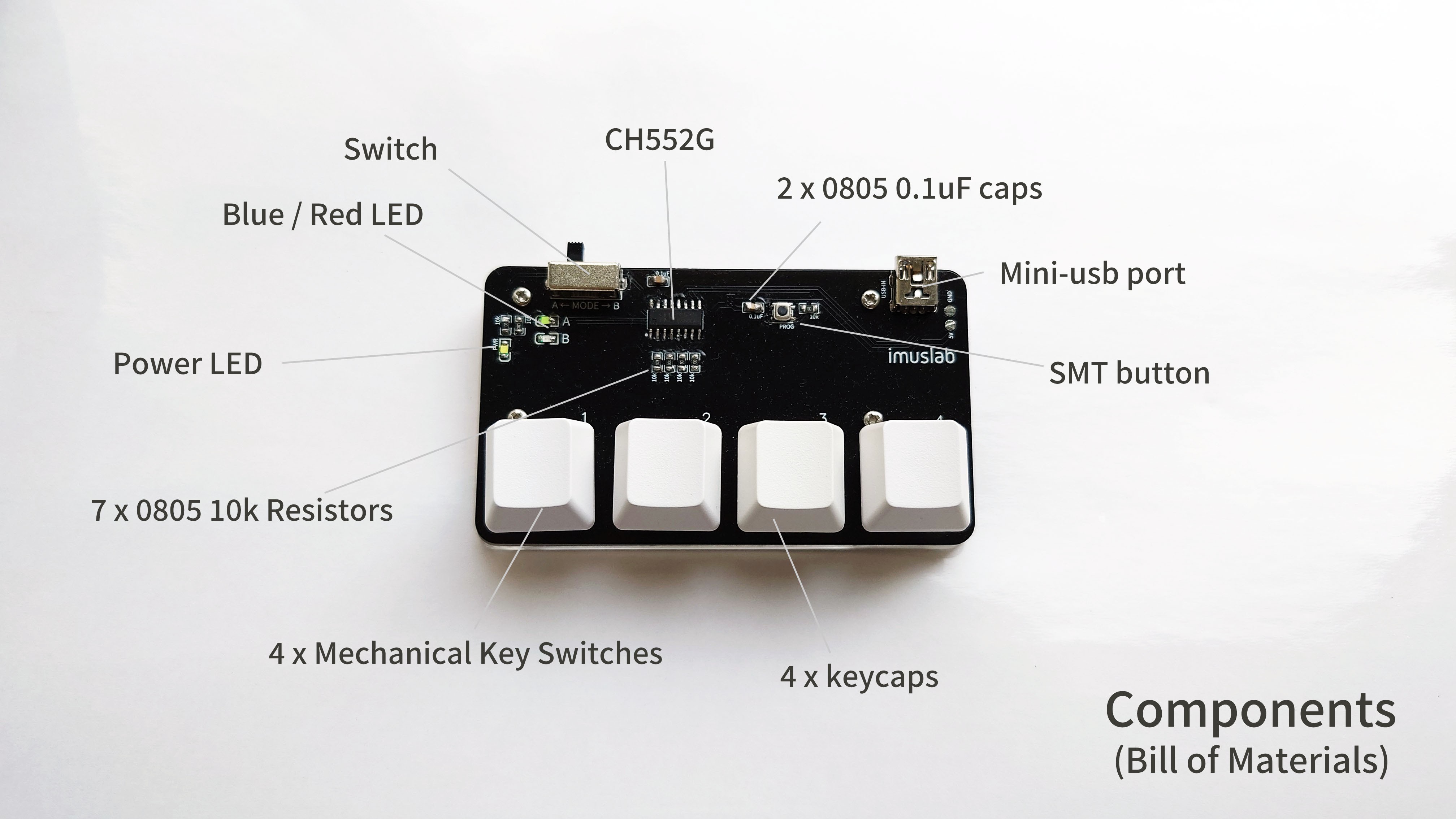
DIY $3 Single Chip Macro Keypad From Scratch

A ch552g powered, single chip, ultra low cost macrokey keypad, compatible with Arduino IDE

Similar projects worth following
I have always been a great fans of Maker Faires around Asia and I am thinking if I could make something special so during maker events, I can exchange gifts with the makers I like so as to start a conversation with them. As a maker primarily working in the software and electronics fields, I really like the idea of PCB business card. However, most of the PCB business card ideas have already been done. From business card that play musics, light or mini game to the magical "My business card run linux" project. I want to come up with a new idea where no one have done before, yet cheap enough so I can afford to build a few of them and giving them out for free.

That is why I designed the "4xMacropad" - The business card size 4 key mechanical macropad. (Technically speaking the dimension is all "business card size" except the height)

macrokey_distribute.zip

The default / testing code for the macropad

x-zip-compressed - 16.46 kB - 04/26/2023 at 10:46

Download

macrokeypad v3.zip

The Gerber file (PCB) for the macropad

x-zip-compressed - 123.15 kB - 04/26/2023 at 10:46

Download

  • 1 × PCB Electronic Components / Misc. Electronic Components
  • 1 × 3D Printed Base Mount
  • 4 × M2 x 5 screws
  • 1 × CH552G E8051 Arduino Compatible MCU
  • 1 × Mode Switch

View all 13 components

  • Numpad? Anyone?

    tobychui04/30/2023 at 04:40 1 comment

    I receive a few DM mentioning that they want a budget numpad based on the CH552G. I am like: Why you need a numpad?

    After chating with one of the person who send me a DM, I notice many mechanical keyboard users don't actually have a full sized keyboard. Instead, they would go with a keyboard without numpad, then buy an additional numpad and only took it out when they needs a numpad.

    However, consider the CH552G. In this project, I am using

    • 2 GPIO for LEDs
    • 4 GPIO for key switches
    • 3 GPIO for RGB
    • 1 GPIO for mode toggle

    So in total there are only 10 GPIO I can use. Is this even possible for me to build a fully functional numpad?

    Maybe Yes, However

    In theory you can use a grid layout to multiplex the number of switches by scanning them line by line. However, conversion design will takes in one diode per switch, which is really expensive in term of soldering jobs. I gonna need to find a way to make it under $5 if I am gonna make one myself :D

    Anyway, if you really want a $5 numpad keyboard, feel free to let me know!

  • Macropad meets Weeb

    tobychui04/26/2023 at 11:32 0 comments

    Recently my friend who went through a head surgery and ask me for one of this macro-keypad. I am like: Sure, it is so cheap and you seems in a terrible mood, you can have one for free.

    So I gave him one. And the next day he told me that he is using his laptop with this keypad so he could be streaming songs and music, control playback from his own server just using 4 fingers, while lying in his hospital bed.

    I am like: Dude, how smart is it you use it this way!

    He also told me he is using this to skip through his anime collection so he could finish the whole 2 seasons of Yuru Camp during his hospital stay. What a cool assistive tech this could be :D

View all 2 project logs

  • 1
    Supplies

    You will need the following supplies to make its macrokey

    1. Custom PCB
    2. 3D Printed base (for mounting the PCB at a tilted angle)
    3. 4 M2 x 5 screws
    4. CH552G E8051 Arduino IDE programmable MCU
    5. Mode switch
    6. SMT button
    7. Mini USB port
    8. 7 x 0805 10k Ohm SMT resistors
    9. 2 x 0805 0.1uF SMT capacitor
    10. 3 x LEDs (Power, Mode A and Mode B)
    11. 4 x mechanical key switches
    12. 4 x key caps of your preference
    13. Soldering tools
    14. Steady hand
  • 2
    Print the PCB and Mount

    The most important part of this project is the PCB. The macro-keypad is designed with a open PCB design, which means the PCB is directly exposed on top of the device, making it a bit scifi style to look at.

    As Instructable do not allow attaching zip file for gerber, I am putting it on Github where you can get it here.

    Gerber File: https://github.com/tobychui/4xMacropad/blob/main/pcb/macrokeypad%20v3.zip

    For the 3D Model file, you can edit it with Autodesk Inventor. They provide a free version for students where you can freely adjust the model based on your need.

  • 3
    Solder the Components

    For starters, I recommend starting from the smallest to the largest components. You can solder starting from the CH552G, then the surrounding 0805 ICs then the other remaining DIP type parts. Follow the silk screen instruction and solder everything in its correct locations.

    There are also 3 optional RGB channel which they can be controlled by advance coding in the MCU. If you want to make some light pollution with those LEDs, you can also solder some extra 10k resistors and 0805 LEDs according to the silkscreen printing.

View all 9 instructions

Enjoy this project?

Share

Discussions

Similar Projects

Does this project spark your interest?

Become a member to follow this project and never miss any updates