Close
0%
0%

The Grimoire Macropad

A macropad build that is probably more trouble than it is worth.

Similar projects worth following
I am in the process of creating a comic. In order to do that, I must create pictures. To make creating pictures easier, I want a macropad. I could order one, but where's the fun in that? Why not build one--not only will it take longer, it will be harder, and might even be of lesser quality! Best of all, it will be built by some nutjob with a slightly elevated sense of his abilities!!

This macropad will have 23 buttons, 2 encoder knobs, a USB-C connection, and a fancy LED light. I will print the body of it on my 3D printer, the Me3rkat (the Mysterious Ender 3 Robotic Konstruction and Assembly Tool).

Allons-y!

I wanted to make this macropad worthy of the work. It should be a work that demonstrates quality. It should be impressive. It should be customized to within an inch of its life. Most of all, it should be such a great thing to look at that it forestalls the question, "Why didn't you just buy one?"

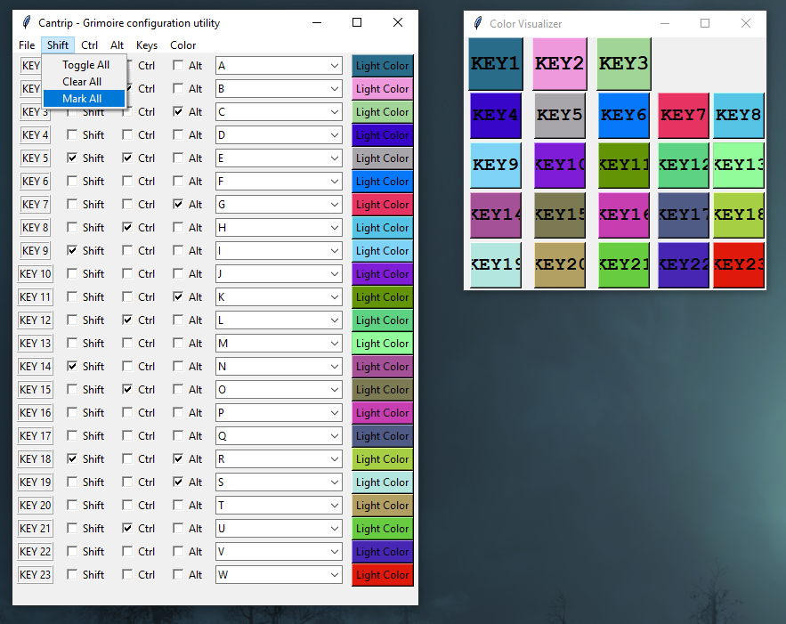
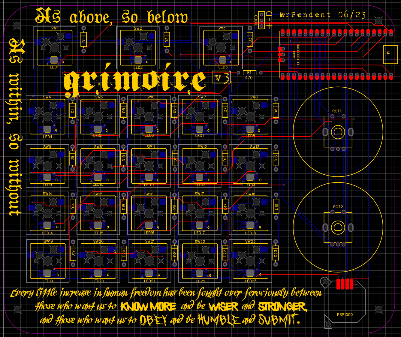
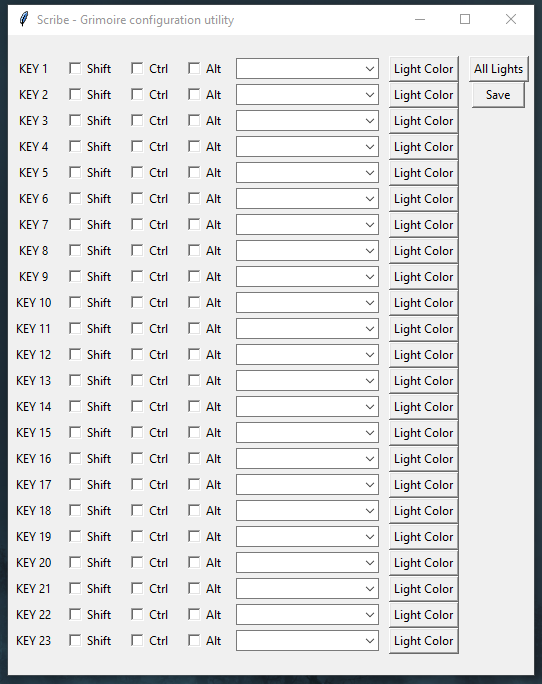
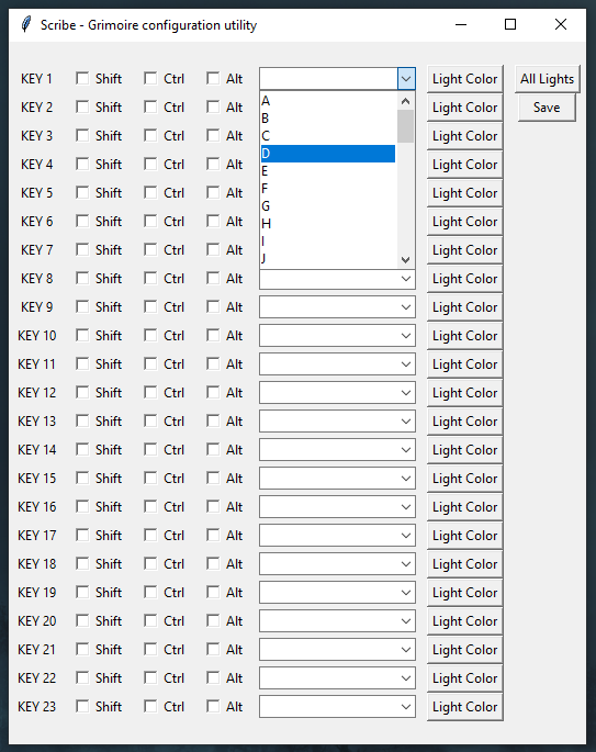
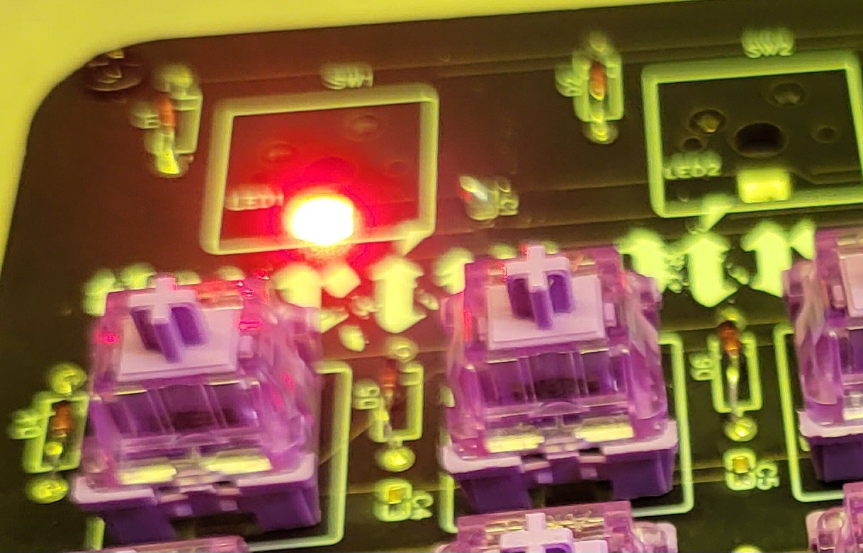
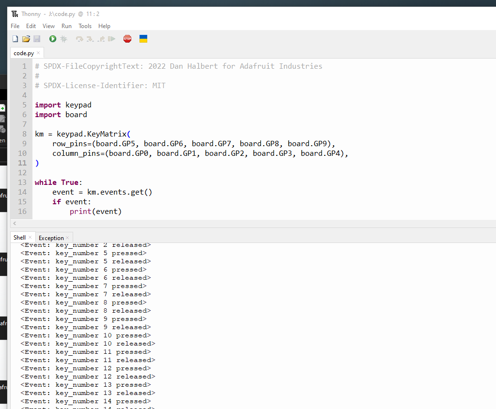
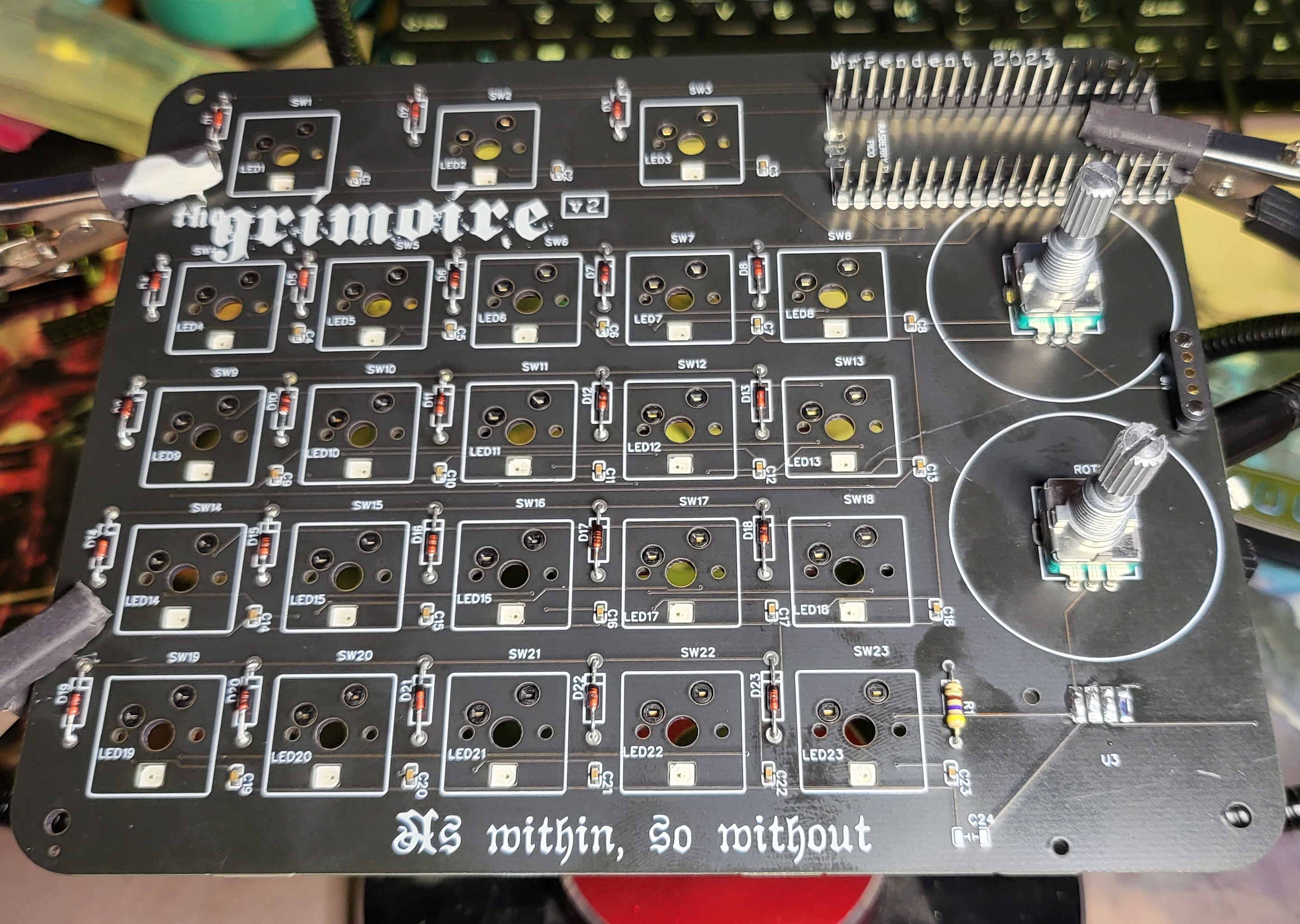
To begin with, we are going to have hotswap mechanical keys for quality and customization. I want 2 encoders--one for brush size and one for zoom. I considered a third for rotation, but I almost never do that, so I'll do without it (or maybe set one of the others to do it too). The three buttons at the top will be for switching between erase, pencil, and brush. The remaining 20 buttons will be assignable.

The name "Grimoire" is because I thought of the keys as each a different "spell" to achieve an outcome.

NOTE: There are no affiliate links on this project.

Schematic_Grimoire mk2 v3_2023-05-20.pdf

Schematic for the Grimoire macropad v2

Adobe Portable Document Format - 163.68 kB - 05/21/2023 at 02:04

Preview
Download

Gerber_PCB_Grimoire v2.zip

The gerber files for the Grimoire macropad v2

x-zip-compressed - 248.47 kB - 05/21/2023 at 02:00

Download

  • 23 × Akko lavendar purple tactile keyswitches Any MX-compatible switches will do
  • 2 × 360 degree rotary encoder
  • 1 × Raspberry Pi Pico / Sumo Pi Pico RPi for micro-USB, but SumoPi if you want USB-C
  • 23 × Kailh MX-compatible hotswap socket
  • 1 × A nOOd flexible LED To light up the sigil area. Not needed if you don't want the glowing window

View all 12 components

  • FML

    mrpendent07/20/2023 at 03:26 0 comments

  • G*ddamn it.

    mrpendent07/19/2023 at 03:33 0 comments

    Be warned that below here is some very salty, spicy language. If you don't like swearing, you might want to skip this.

    Read more »

  • We can't go on together...

    mrpendent07/18/2023 at 01:42 0 comments

    Friends, we are at the end of an era. I have redesigned the PCB, and STILL can't get these %$#&@! Neopixels to work. I don't know what the problem is, but I am past caring. The keys work just fine, and that's the functionality I want. I could order another PCB without the lights, but I don't really see the point. It will work fine with faulty Neopixels,

    I'm just sick of fucking with it. I need to get on with my work, and this is becoming an impediment. So I will get the coding done, then build the shell, and then go on with my life. If I have the time/energy/fucks to deal with the lights later, I will. Otherwise, I will ignore them.


  • It's tricky! It's tricky, tricky, tricky!

    mrpendent07/06/2023 at 01:16 0 comments

    The config utility has been updated.

    It's name has been changed to "Cantrip". Although I liked "Scribe" (because that would be how you would record items in a grimoire) but Cantrip sounds a lot cooler. And if this project is about anything, it's about style over substance.


    So here's a glimpse of it now:

    There's a lot here, so let's have a look:

    • A menubar
    • File menu: open, save, and an "About" window
    • Shift/Ctrl/Alt menus: Each have the same three options--toggle all, clear all, or mark all
    • Keys menu: Has options to assign keys in alphabetic order (as seen) or clear them all
    • Color: Allows for assigning one color to all keys, all black (well, grey), all white, or random colors (shown). Also includes a "Visualizer" so you can see what the layout will look like on the Grimoire

    Obviously there is still work that needs to be done, but it's coming along. Right now it can open a file, read it, and dump the contents to the console. Not particularly useful, but...

    TODO: Cantrip

    • Fix the fonts in the visualizer
    • open the code.py file and assign the values/colors inside to the controls in Cantrip
    • save settings in Cantrip to the code.py file

    Once I get these things done (and the board built) it will be time to work on the shell. Getting closer and closer

  • Put one foot in front of the other...

    mrpendent07/04/2023 at 14:41 0 comments

    Version 3 of the PCB has been ordered and should be here in a week or so.

    A few changes:

    • the minicaps have been removed from the LEDs
    • the ground pin on the Neopixels has been marked
    • the pins for the add-on light have been labeled.
    • I got to do a little more decoration since I had some largish spaces.

    I have also built the first part of the configuration utility, written in Python:

    The three checkboxes allow the user to assign those modifiers (or any combination) to a keystroke.  The drop-down allows the user to select a key:

    The "Light Color" button allows the user to select per-key light color. The "All Lights" colors all the lights the same color.

    "Save" isn't completely working right now. At this point, it builds a string of all the selections and colors, then dumps it to the console. Later, it will open the code.py file on the Grimoire, erase any existing settings, and insert the new ones, then close the file and reboot the device (somehow). I'll be working on that while I'm waiting for the new board.

  • The sun will come out, tomorrow...

    mrpendent06/25/2023 at 18:28 0 comments

    Knowing(*) that my LEDs are screwed due to the "protective" caps I put in, I have been reworking my schematic and gerber files. To test this, I bridged a cap with some solder, added some code and...

    Blurry, but lit!

    Next, I wanted to be sure that I had at least gotten the keys right (for my own bruised ego, if nothing else).

    So a little more coding and...


    A couple of the keys didn't register, but since others in the same row and column did, that's surely just due to poor soldering so I'm not worried.

    I will finish up the new gerber and get it sent off, then maybe make some actual progress on this thing. When I send it off this time, I will have the diodes, hotswap sockets, and NeoPixels (I hope) added at the factory. Allons-y!


    [*] According to a smart and friendly fellow by the name Ken Yap, it seems there is an issue with the LEDs having caps preventing them from getting power.
    File photo of Ken Yap (may not be current)

    I put those in because of the adafruit überguide. Lady Ada is certainly smarter than me, but the guide seemed to be more aimed at people hooking up multiple strips of neopixels to a car battery, or directly to a power outlet, not linking a single pixel to a usb port. At any rate, I'm glad to be able to skip that and move on. I think the third PCB will be the charm.

  • Ain't that a kick in the head...

    mrpendent06/20/2023 at 22:12 2 comments

    Sooo...I received the replacement parts, and this time decided that I would put one pixel and the Pico on the board, then try to get it working. At that point, I will put on the other pixels.

    Well, that was the plan. The reality is...a little different.

    I put one pixel on, then soldered on the Pico. I put in the cap that was supposed to be there (according to LadyAda). Then I tried some programming.

    I was able to get the on-board LED to light up through code, so that was good.  Then I set my sights on the Neopixel.

    I soldered it on, then tried the pixel code--no light.

    I got the gerber file out and followed the trace to be sure that the one I had soldered on was, in fact, the first. It was, but still no glow.

    I put on the other two in that row, just in case it had been run differently somehow. No glow.

    I put the last one on in case it was going the other way. No glow.

    At that point, I put it away to think about what was going on.

    I came back to it today with an idea--I got some wire, and soldered a pixel directly to the Pico, to the same pins that the other pixels are on. And:

    So...this tells us that my understanding of the pixel (and my code) is correct. I ended with this code:

    import time
    import board
    import neopixel
    import random
    
    num_pixels = 2
    pixel_pin = board.GP18
    
    pixels = neopixel.NeoPixel(pixel_pin, num_pixels)
    pixels.brightness = 0.5
    rnd_r = random.randrange(0, 255)
    rnd_g = random.randrange(0,255)
    rnd_b = random.randrange(0,255)
    
    print(rnd_r)
    print(rnd_g)
    print(rnd_b)
    
    COLOR = (rnd_r, rnd_g, rnd_b)
    
    while True:
        pixels.fill(COLOR)
        pixels.show()    
    

    (The random numbers are there so that every time it runs, the color will change and I will know that the new code is running (or at least a new version of the code).)

    It also tells us that the problem is between the Pico and the pixel. So that means it could be:

    1. a problem with the soldering of the Pico to the board.
    2. that the Pixel isn't fully connected to the pads on the board, though I've tried everything I can to be sure
    3. that, while trying to ensure the pixel is connected well, I've managed to fry it.
    4. a design problem with the board itself

    The easiest thing to do is to use a multi-meter to check is the trace on the board. So I'll do that next.

  • Listen all y'all--it's SABOTAGE!

    mrpendent06/07/2023 at 02:15 0 comments

    Well, ok...maybe self-sabotage. But still.


    I'm sure this is because this whole project is slightly beyond my abilities. But as I said at the start, I knew that was the case. That was kind of the point. Why bother with something I already know I can do?

    So here's where we are:

    I'm sure there is a way to desolder surface-mount items from a PCB, but I also know (now) that it is beyond my abilities. Which is fine--neopixels don't cost that much.

    I have used (read: ruined) 2 of my 5 PCBs. Which is fine. Either I'll get one of the remaining ones right, or I'll pay for the neopixels to be soldered at the factory on the next ones.

    I need to order some more parts, so we'll be going into torpor until those arrive. I need to re-order the following: 23 Neopixels, another magnetic connector, more encoders, more Kailh sockets, and more switching diodes.

    I just keep telling myself that it will all be worth it in the end.

    It will be worth it in the end.

    It will.

    I mean it.

  • INTERLUDE: A little mathematics problem

    mrpendent06/05/2023 at 15:18 0 comments

    You begin with a field of four options--A, B, C, D. 

    You pick one--let's say C. 

    You randomly pick 23 options out of the field of four. 

    Of the 23 random selections, how many do you expect to be C?

    Read more »

  • Sangro todo lo que escribo

    mrpendent06/05/2023 at 02:38 0 comments


    So....neopixels, huh? Those things are tiny. Very tiny. On the first first board, I got the diodes installed, then the sockets, then 3 neopixels. On #4--SHENANIGANS!!

    While trying to remove a messed up led, it actually peeled the solder pad AND the trace off the PCB.  So I had to start again. The second time, I carefully put all the Neopixels on first (thanks to some advice from Ben Heck):

    Then the sockets...


    Then the diodes, encoders, and headers...

    I had one issue--the joystick holes seem to be 2mm (I think? Maybe 1?) and I don't have screws that size to mount it. so I got the pads ready, but can't mount it yet. I'm a little worried about it still, but fortune favors the foolish. I love the look of the diodes--the translucent red with black ends remind me of some of the carpenter ants that I would see back in NM.

    Next up:

    • Get some screws for the joystick
    • Figure out what goes at C24 (the symbol is a capacitor. I think it was a 1000 mF cap to protect the LEDs)
    • Install the SumoPi and give it a test

    I'll be honest--I'm a bit scared of the last one. If it doesn't work after all this, I will be disappointed.

    ps. Just a little image. Ignore this.

    Nothing to see here.

View all 22 project logs

Enjoy this project?

Share

Discussions

Similar Projects

Does this project spark your interest?

Become a member to follow this project and never miss any updates