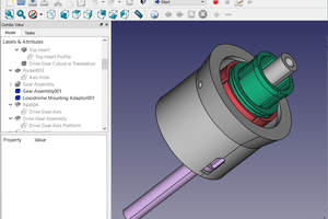
CAD Design
The physical structure for the dice is 3D printed.
It will be made up of six identical sides, each containing seven holes to allow the LED's to be positioned to form the dots in the dice and a cylindrical section to support the coil and mount the side on a central support cube.
The central support is a hollow cube with holes passing through each face to accomodate the sides of the dice.
Once the sides have been assembled on the central support the completed elements are housed in a cube consisting of two parts, a main body and lid. No markings are made on the cube surface to identify the numbered sides as this is indicated by the illuminated LED's.
The purpose of the hollow cube is to help support and strengthen the elements of the die, diffuse the light from the LED's and enhance the randomisation.
Circuit
The basic circuit design is the same for each side, an air core coil and parallel wired LED's the quantity depending on the side associated with the die pattern required for the represented number.
The red LED's are surface mount 2mm x 0.775 mm.
The sides are arranged in pairs such that the sum of the LED's on each side adds up to seven.
Coils are connected in such a way that they drive the LED's on the opposite side of the cube.
E.g The coil on the six side lights the LED on the one side and the coil on the one side lights the LED's on the six side.
The coil (~270uH), is made up of ~200 turns of 0.15mm (dia), ECW wrapped on the central form on the back of each side element.
Usage
The inductive dice is thrown in the same way as a standard dice. However, it must land on a wireless charger within the central area encompassing a radius of ~26mm for effective iilumination.
This may be difficult to achieve without an enclosure to contain the dice or simply placing the dice on the charger.
Simply rolling the dice picking it up and placing it on the pad will work unless the sides are marked allowing the numbers to be known removing the random element.
However, an enclosure designed to contain the dice within the central area of the wireless charging pad has been created but that is the subject of another project.
 marciot
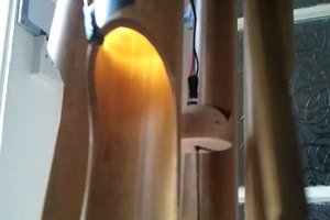
 matt thurstan
 Michael
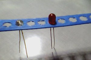
 Alois Mbutura