This all started from wanting to add motion to my timelapse's but didnt want to shell out half a grand for something i could build myself. this also allows me to add features only seen in expensive timelapse controllers such as joystick control for the position as well as exposure control through the timelapse controller. the hardware and software began around the same time.
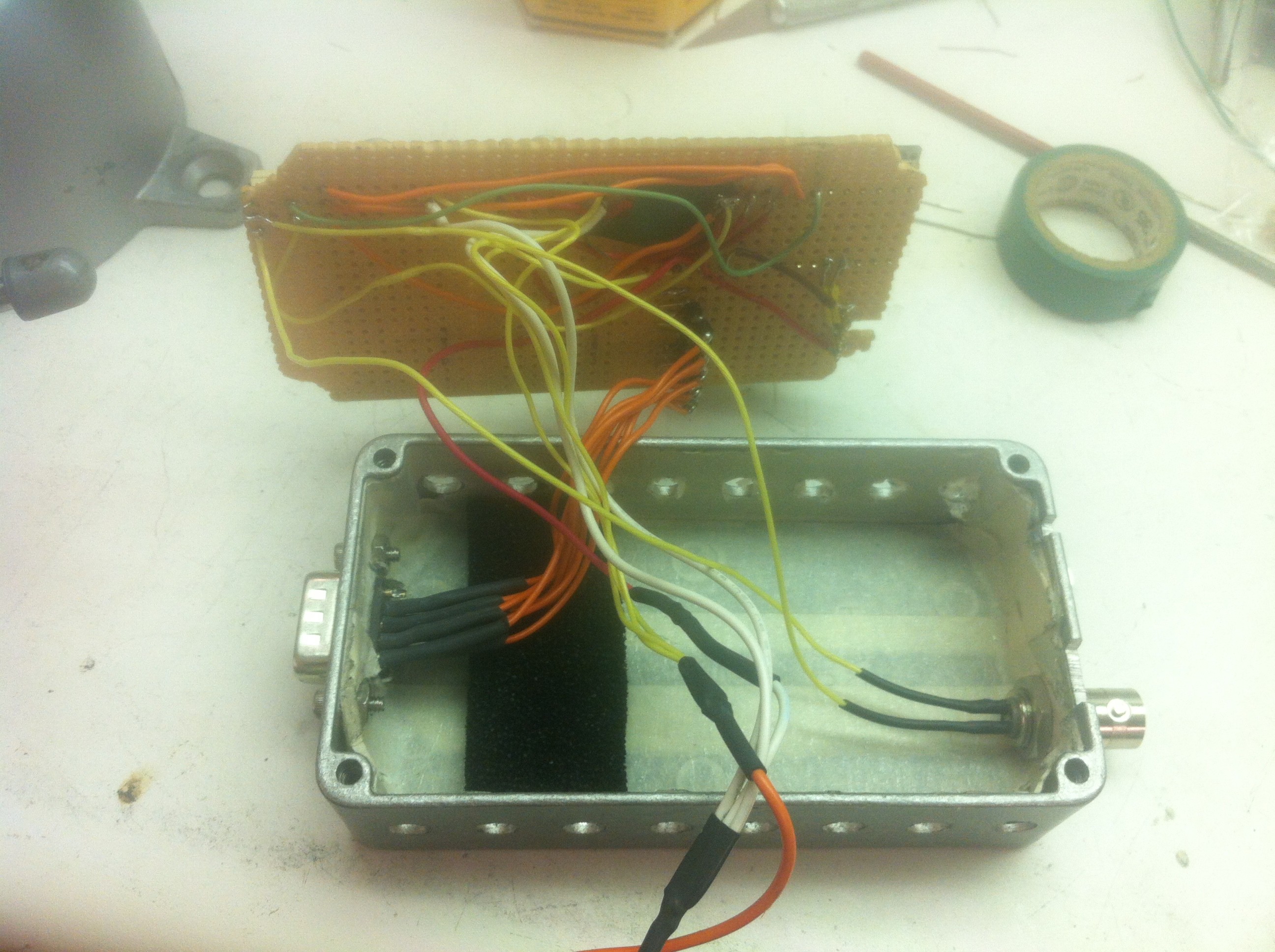
heres the start of the controll box that houses all the electronics for operation. inside i have fit an arduino micro, two easy drivers from spark fun, a joystick and 4n25 optocoupler chip to trigger the shutter on the dslr camera. this all fit nicely inside a small metal box i found at work with the motors cables exiting the enclosure through a DB9 cable and the shutter control cables through a isolated bnc connector. the bnc connector is alittle overkill and in future versions ill have the shutter cables and motor drive cables all come out from one connector on the box.
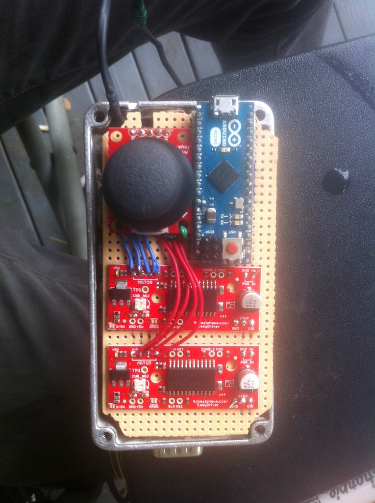
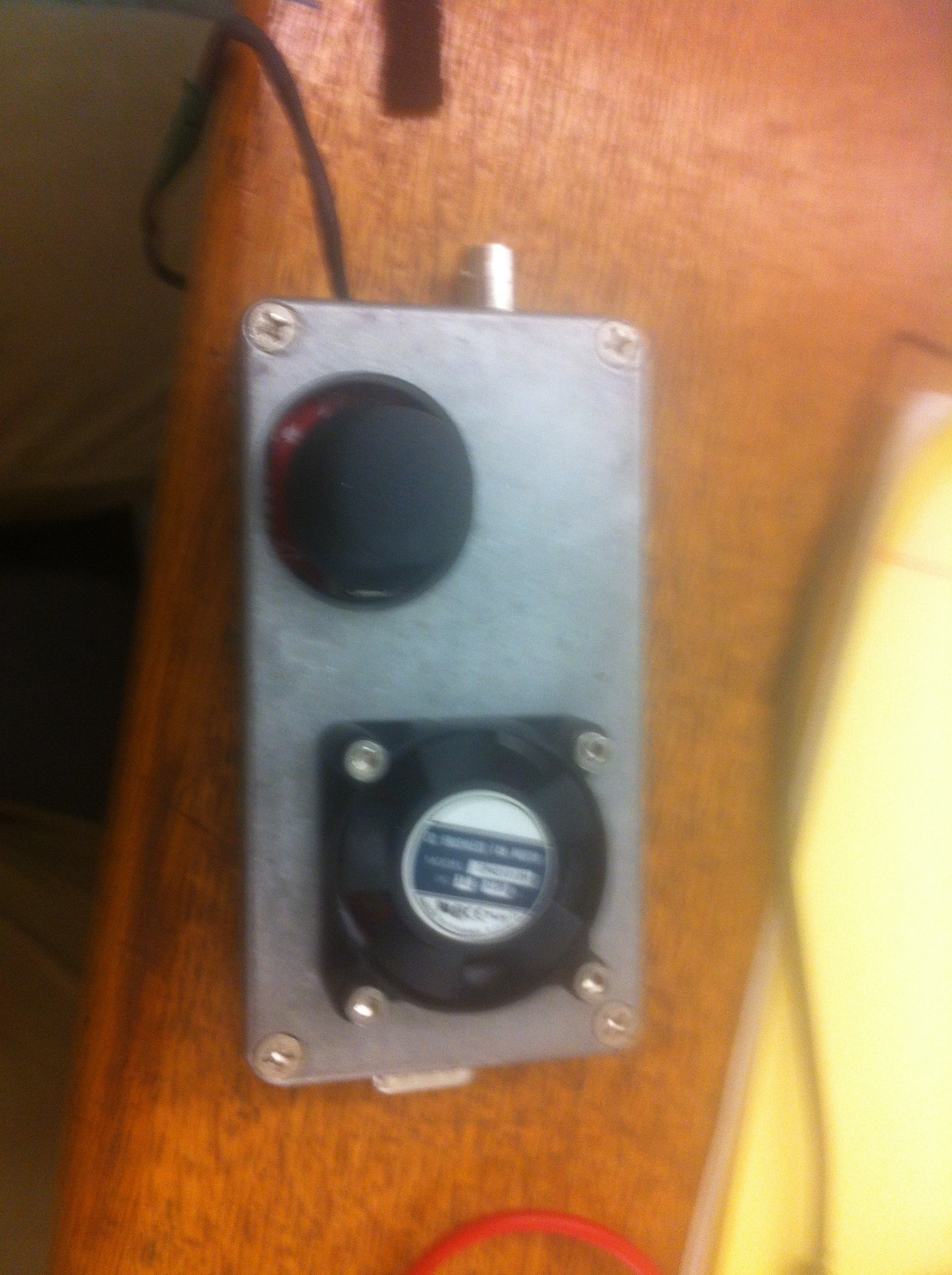
heres the wiring almost done, most of its under the protoboard as well as all the power cables. only thing left is the 4n25 optocouple to wire up to a digital pin and ground on the arduino. a 2.5mm headphone jack was found at a local electronics store that is used to connect the dslr remote trigger cable. once all the wiring was finished i began testing and writing the control code. it was decided to add a small 12v fan to the outside of the controller box to manage heat coming off of the easy drivers during long timelapse recordings. the finished control box minus connector cables for shutter and stepper motors: (sorry for crappy camera phone pics)
alittle extra about the wiring:
1) all heat shrunk soldering since i shorted an easydriver in the early stages
2) everything powered by same 12 V source coming from a rechargeable motorcycle battery (highly recommend getting one of these for projects that need to last long hours) joystick getting voltage from 5 V arduino out
3) vent holes drilled on side of box to allow air flow
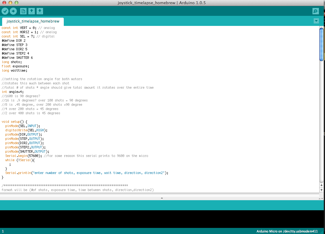
The code:
pretty simple really, i have no problem supplying the code to those who want it just comment below or shoot me an email. its still somewhat a work in progress since i want to add more features and options. basic layout: its using digital out pins 2-7 on the arduino, 2-5 are for the stepper motors, 6 is the camera shutter, and 7 is the joystick select. reads in five serial commands that establish direction for each motor, how many shots to take, the exposure time, and the wait time between shots. steps taken per shot by the motors is defined in the code and not through serial so i can have each axis move a desired amount independently of eachother. loop order is as follows: read in serial, take first photo for desired exposure time, wait half a second, move steppers set amount and direction, wait time between shots, take second photo, repeat. joystick select button when pressed will trigger the camera shutter as well which helps when setting up the start position of the timelapse and correct camera settings. as of right now there are three different exposure settings that the user can choose from based on the serial data input: normal constant exposure for entire shot, linear gain or decay exposure setting for changing light during the shoot, exponential gain or decay setting for changing lighting during the shot. the joystick is read in through two analog input pins on the arduino and the values are mapped to allow varying movement speed of the timelapse head based on how much the joystick is moved.
All the codes very flexible and easy to manipulate for different settings.
(future pans include a more powerful processor to allow for long exposure milky way tracking timelapses as well as object tracking using a embedded linux platform (RPI or BBB) with camera addon controlled with opencv, and touch screen interface)
Mechanical:
Parts were hand machined by myself on a bridgeport knee mill or lathe, all 6065 aluminum. bearing are sealed type. toothed gears and belts were purchased from Mcmaster.com, gear down the stepper motor movements by four times allowing very precise and small movements between shots. very compact package means i can fit everything including battery and tripod inside a standard sized backpack while the construction allows for very heavy cameras to be mounted (only tested movements with up to six pounds on rotating head).
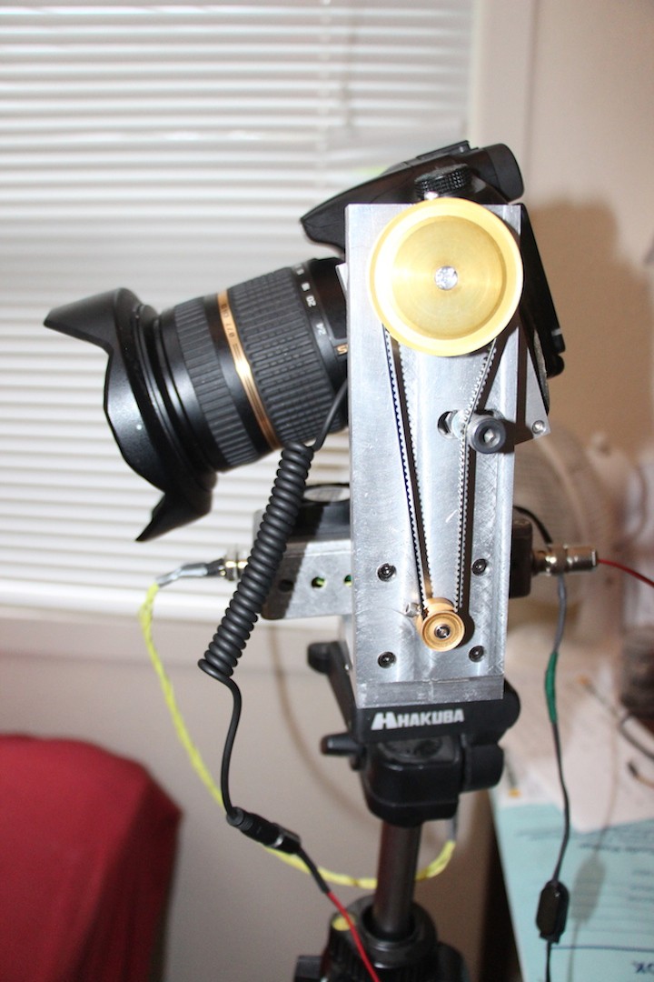
added tensioning bolt on the vertical axis to remove any wiggle or slop from using a 4 inch diameter belt.
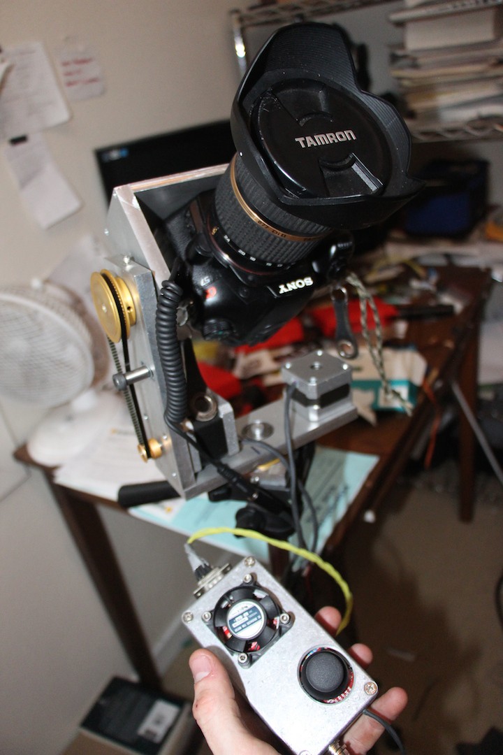
operates very well even with camera upside down. As you can see in this photo the camera mount doesnt allow for fine tuning of the cameras center of gravity on the rig itself and a better mount is currently in the works.
Discussions
Become a Hackaday.io Member
Create an account to leave a comment. Already have an account? Log In.
Hi there.
I really like your project. This is exactly what i planning to do. Now I teach only work with Arduino. But I've had pretty good progress. I would be very pleased if you can send me your code for inspiration.
Thx.
Mayo
Are you sure? yes | no