Close
0%
0%

hRobot

open source, connected, 3D printable robotic arm, powered by ROS, with 500g lift capacity

Similar projects worth following
It’s an Open Source and printable manipulator with five degrees of freedom. The main purpose of this project was to create a robotic arm that could be made by makers around the world or in schools to teach robotics instead of using simulation software. In its upright position, hRobot is about 700mm long and it can lift objects up to 500 grams. While development we had many ideas in our minds like:

1. the final prototype had to be Open Source,
2. possible to made mostly by 3D printer,
3. enough powerful to manipulate 500 grams objects
4. and powered by ROS.

We hope that you will enjoy our work :)

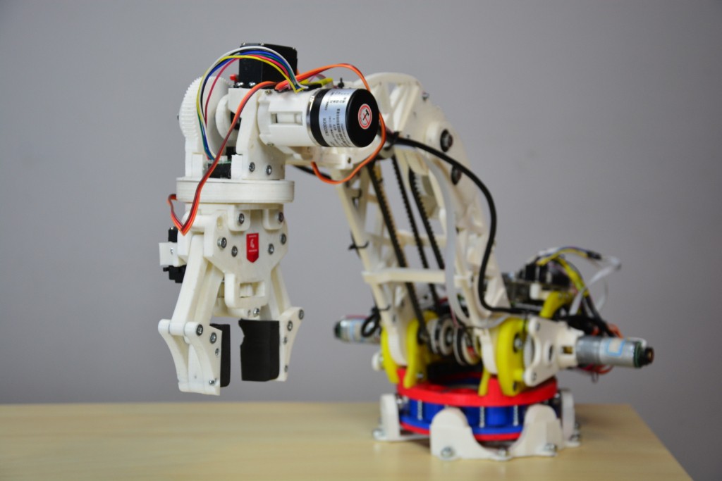
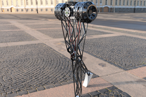
Project was designed and created by Mikowhy95, zaba963 and Hubert424 . The controller used in hRobot is a Husarion CORE2 in a configuration with a Raspberry Pi. The arm uses DC motors, servomotors and quadrature encoders. In files you can find all parts in STL format ready to print. Video shows very first version of our robot.

As you can see not everything is working right now. For example we have to recreate the gripper because stepper motor used in this version is not strong enough.

We are still developing a software but it can take some time, to make this fully functional. That's why we haven’t shared a code now. We will publish code on github.com, and we hope people around the world will join our project!

STL_v1.rar

Set of STL with all parts of hRobot v1

RAR Archive - 1.94 MB - 12/23/2016 at 13:00

Download

View all 8 components

  • We added limit switches and it’s not only about safety

    Mikołaj05/01/2017 at 17:26 0 comments

    Automating and simplifying procedures are the basis for speeding the processes up. For example, fixing the starting position after reset. It is necessary, because the readings from the encoders that we use are only relative, so every time we turn the robot on we need to point out the absolute position that robot has. Specifying this position manually would took a lot of time, because it is very difficult to measure angles of each joints. The better way is to put robot, with a small steps, to the specific position we can identify, like (0,0,0,0,0). Then we say ‘Now, dear hRobot, you are in start position of (0,0,0,0,0)’.

    And now, how to speed up this process more? Read again first sentence - of course we need to automate and simplify as much as we can! We use end switches to detect the extreme position of each joint or to find characteristic point (in case of continuous rotation). This position of all hRobot’s elements is stored once and then used as a reference.

    Video that shows how it works in reality is coming soon.

  • Struggle with linear interpolation

    Mikołaj04/27/2017 at 10:42 0 comments

    The next big step to take during the second approach is to force the robot to follow a predetermined path. How? Using a linear interpolation. Although with the joint’s interpolation there wasn’t any huge problem, this time it's completely different. Let me start the explanation with a little bit of theory.

    When the robot is at the point P1, and its aim is to move to the position named P2, it has two ways to reach the target. With joints interpolation or with linear interpolation. In the first case the manipulator calculate an angular path of each connector. Let's say joints parameters of position P1 will be 0 deg in J1, 20 deg in J2, -15 deg in J3, 0 deg in J5 and the same in J6. To simplify the notation we will use registration like these: P1(0 20 -15 0 0). And so, the second location is: P2(0 -10 0 10 0). Algorithm will calculate the differences, for J2 it’s -30 deg, for J3 it’s 15 deg and for J5 it’s 10 deg. We know maximum speed for each joint, so we can calculate the slowest change. In our example, the second joint has the longest way to travel, but the slowest joint during this movement is the third one. Therefore we need to divide our angular path of each joint and spread the resulting points accordingly over time to adapt the speed of the resultant movement to the slowest of the joints. It is worth mentioning that all the calculations take place in the joints positioning system, so if P1 and P2 are given in cartesian coordinates, they should be converted into a joints coordinates. How the geometry calculation class works is a quite long story, great for a new topic.

    Returning to the previous topic, why linear interpolation is so complicated? Well, first of all, all iterations of interpolation are calculated in cartesian coordinates. This fact alone is nothing significant, because these coordinates are just scalars, so we can divide the path to small vectors and convert them to discrete path made of many points. But now, every of the resulting point have to be calculated to joints positioning system. And due to the fact that the calculation of inverse kinematics is the most difficult task for the controller, it complicates us the whole job. Another trouble is speed setting. During the way from one of resulting mid-points to another with the same linear speed, all joints have a different angular speed (and it’s changing over time). So, if we want to maintain the linear speed of the gripper during the whole movement, we need to predict unknown for us speed of the slowest joint.

    However, the calculated points, and especially in this case, settings of each joint, are sended to the motion controlling class. Positions of joints are controlled by independent PID regulators, so in true these coordinates are just an indication of where we would like to place gripper at the right time.

    What we could or better should do is to make the algorithm that takes into account also the acceleration of the movement.

  • ​We finally finished joint interpolation and created a repo for hRobot at GitHub

    Hubert03/04/2017 at 00:39 0 comments

    Last time we described problem we have to deal with during creating hRobot. We fixed most of them and we are ready for a little demo. Video below show one of possible use cases :). It is of course much more universal. Find out for yourself.

    Robot uses joint's interpolation while moving from one place to another. Implementation of this part of code was quite difficult and really time-consuming. Interpolation allows hRobot to move more smoothly.

    On https://github.com/husarion/hRobot you can find the last version of working software. It will be improved in the following weeks, but even now it’s stable. We are going to add cartesian interpolation in the next weeks.

  • Problems we had to deal with

    Hubert12/28/2016 at 18:11 0 comments

    When we were creating hRobot we had to face a lot of problems from many different reasons. Now I want to tell about some.

    #1. Problems with 3D printer.

    If you think about making a big 3D printable project, you have to be sure your device is suitable for it. For example cases with stopped print or problems with extruding filament are completely normal for bad printer. Sometimes it’s better to invest more money in your equipment then wasting your time on repairing old one.

    #2. Burned servos and DC motors.

    Errors in code, overheating, improper connection - all of it can result in damage of motors. Sometimes it’s not even our fault, it can be just a factory defect, so if you order that things, think about some spare pieces in advance!

    #3. Wrong strength calculations.

    When you printing some parts of your robot, not always piece which looks exactly like other one have the same strength properties. Difference can come from another printer settings, time of cooling and few other factors. So you have to adopt bigger margin of error then you used during strength calculation. In other way part can be badly damage.

    As you can see creating robot can be little a bit difficult, but it’s really worth all of this efforts and brings so much fun!!!

    Next log soon...

View all 4 project logs

Enjoy this project?

Share

Discussions

Florian Festi wrote 11/30/2017 at 20:24 point

The arm could become a lot stiffer if you added some diagonal cross beams on top and bottom of the arm. As it is right now you only have two time the strength of the side walls instead of the stiffness of the full width. It is even visible in the video that the arm flexes when moving left to right. Even beams much thinner that the ones in the side walls could easily prevent that.

  Are you sure? yes | no

Similar Projects

Does this project spark your interest?

Become a member to follow this project and never miss any updates