John Wetzel
When I set out to make this, I based my initial design on what was either a very poorly remembered schematic or a fever dream about a technique used to control the gain of a cassette recorder. I'm absolutely sure there is some reason why this isn't supposed to work, but I don't know what that might be. Something to do with transconductance maybe.
Either way, I set out to make a compressor that could be made out of just about any junk you have laying around. Despite the fact that it uses a lm324, it manages to avoid the disadvantages of doing so by not using a ton of gain and by biasing the output so that it's *mostly* class A. I let the stray transients break through into crossover distortion because it represented a significant power savings while having relatively little impact on cost.
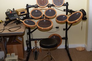
I am working on another project that's a percussive instrument that has a very high dynamic range which introduces a lot of problems. Internally, it has a 3W power amplifier and a moderately powerful headphone amplifier. While 3W can play studio produced music quite nicely, an actual percussive instrument has a much higher dynamic range with a very sharp attack. I had considered just adding a soft clipping circuit, but this doesn't seem to produce a very pleasant sound at all with bright sounds like hi hats and cymbals.
The main control element being a transistor introduces some interesting distortions. When heavily driven it becomes less of a compressor and more of an overdrive. I think this is likely due to the base collector juction diode reaching it's conducting voltage and clipping the compressed signal. The interesting thing about this is that the envelope accounts for this as gain reduction, so in theory at least it must be bringing the gain up again after the signal drops off distortion.
To save on parts, the rectifier is just a single op amp, no "precision rectifier" circuit. This likely introduces a saturation signal hang, though it's possible this dissapears when the signal drops .7v across the diode into the passive section of the signal. It's also a half wave rectifier, because, again, lower component count and cost. This disadvantage of this is added distortion and the occasional missed cycle at the start of a transient. This also requires that the op amp in question is able to operate down to the 0v rail. This meant that my options were reduced to rather expensive op amps that I didn't have, and the LM324, which I did.
It was a complete accident that I found that two transistors driven by the same element cancelled most of the distortion of the previous stage and nearly eliminated low frequency bleedthrough. To futher reduce distortion I added some of the original signal back in at the last stage. It should be noted however, that this stage drives the envelope with this signal already mixed in. This seems to have altered the compression characteristic to instead of squasing the upper peaks and making up volume, it now seems that it's adding volume to the valleys of the sound.
It seems to handle percussive sounds well enough, adding it's own distortions to the mix . It sounds okay on guitar with a much better noise level than expected, but I think it's a little too fast for it's own good here. If I were to make it again or modify it with this as my intention, I would probably increase the size of envelope capacitor significantly - guitar sounds ok with a little bit of added attack.
 The Big One
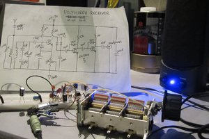
 morph
morph