I will have to experimentally determine how much spring force is required to keep the ring pressed against the mat board while the knife is being plunged into it. To aid in this the current design allows 3mm of over travel after the ring touches the mat board. Of course that amount can be adjusted by reprinting the mount plate and using slightly longer linear rails.
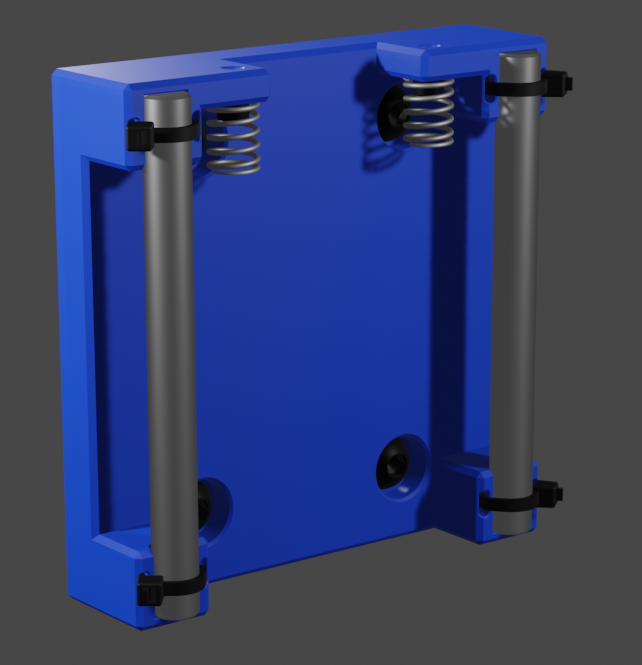
The blade plunges into the mat board at a 45 degree angle by using a stepper driven lead screw to force a driver down on a slider that is guided down at the required angle.
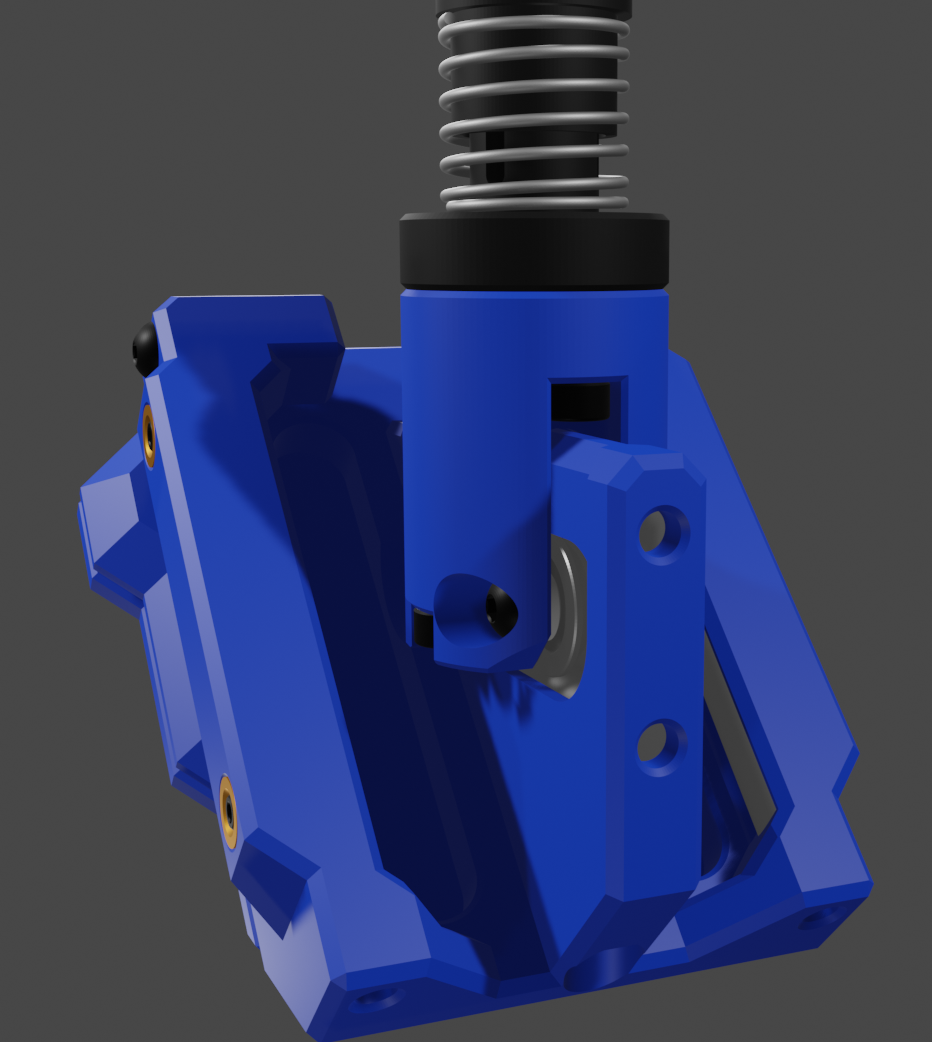
The slider and driver interfaces are through V623ZZ V-Groove bearing riding on hardened 5mm shoulder screws that can be inserted and removed for assembly and disassembly. The slop in these linear rails can be adjusted with grub screws that push the shoulder screws into the fixed position V-Groove bearings.
In order to place the bearings as accurately as possible I cannot use brass threaded thermal inserts (which I prefer for 3D printed parts that will be assembled and disassembled multiple times) I will instead leverage the accuracy of the 3D printer to place slightly undersized holes for the bearings. I can then mount the bearing with screws through the printed holes into nuts.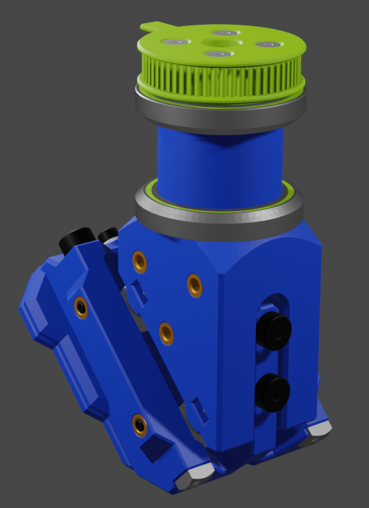
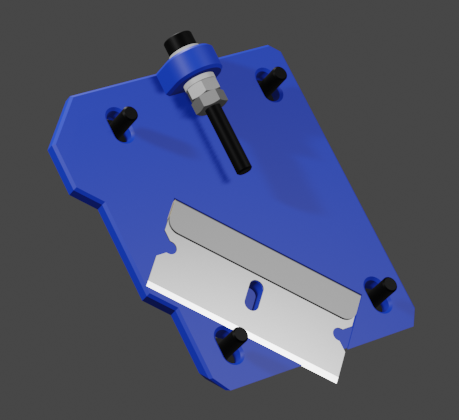
The knife will be pivoted around the vertical using a stepper motor and bicycle headset bearings that seat into tapers.
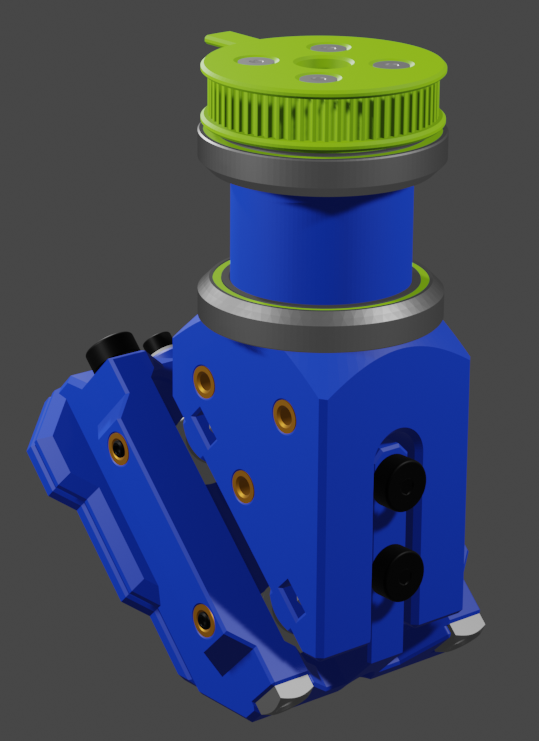
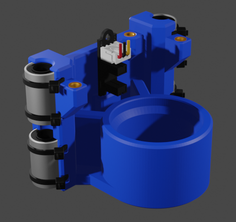
Both the GT2 pulleys for the lead screw and the knife pivot have flags on them to trip the optical limit switch mounted to the pivot bearing block. With two flags and only one switch some care will be required to "home" the head, but should be doable. Also the design necessitates that in order to maintain a consistent depth while pivoting the knife the lead screw will have to be rotated in sync with the knife pivot. This is fairly simple with both the lead screw and pivot GT2 pulleys arrangements being the same size. Using 20 tooth pulleys on the stepper motors and 60 tooth pulleys on the lead screw and pivot gives a 3:1 "gear" ratio that results in 0.3 degree pivot resolution and 0.007mm depth resolution with half stepping.
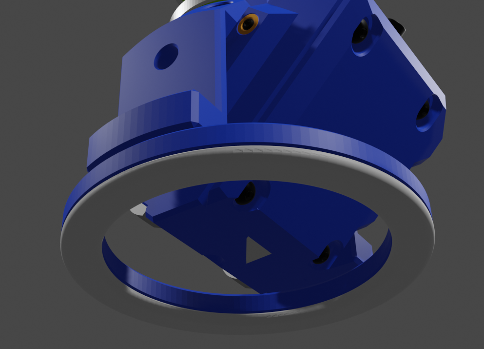
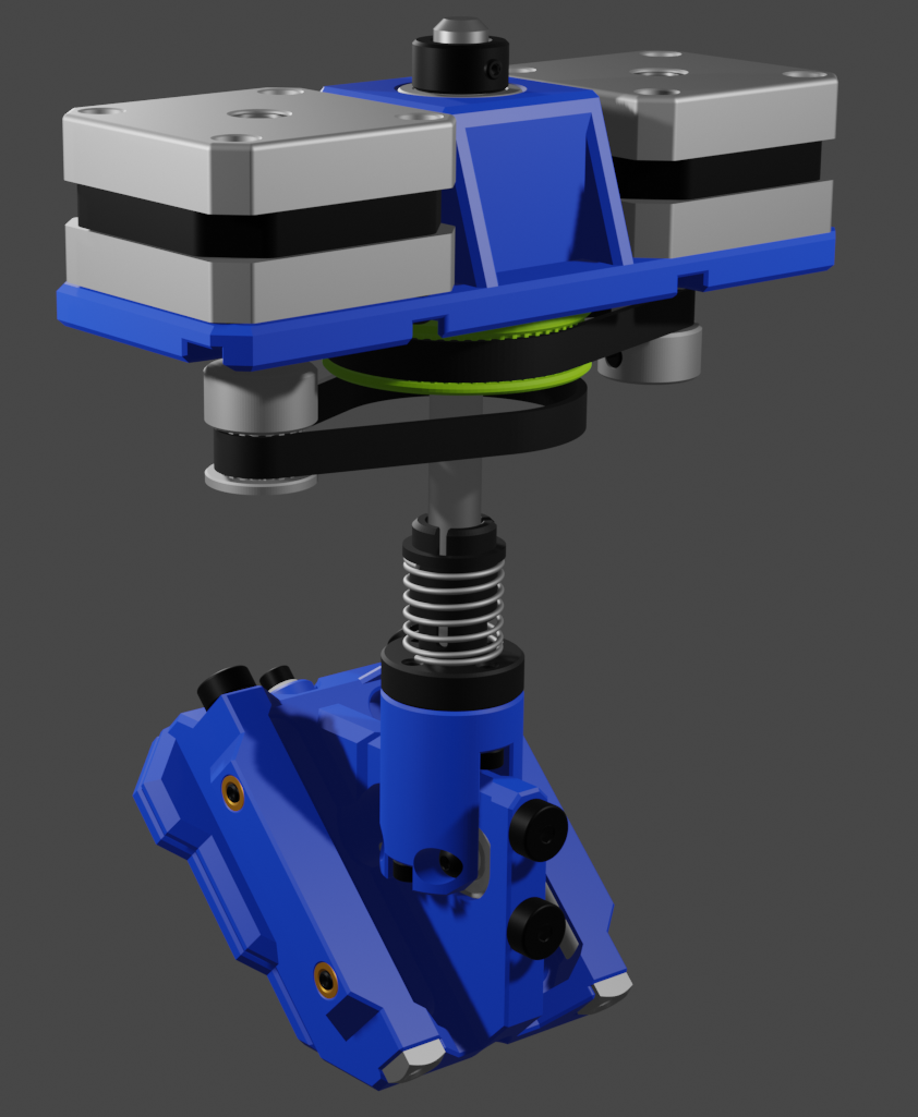
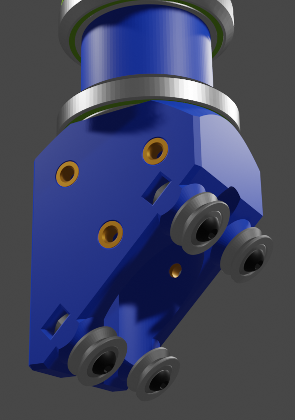
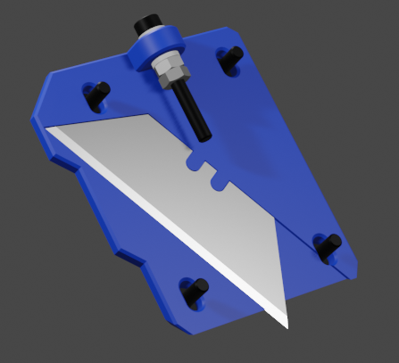
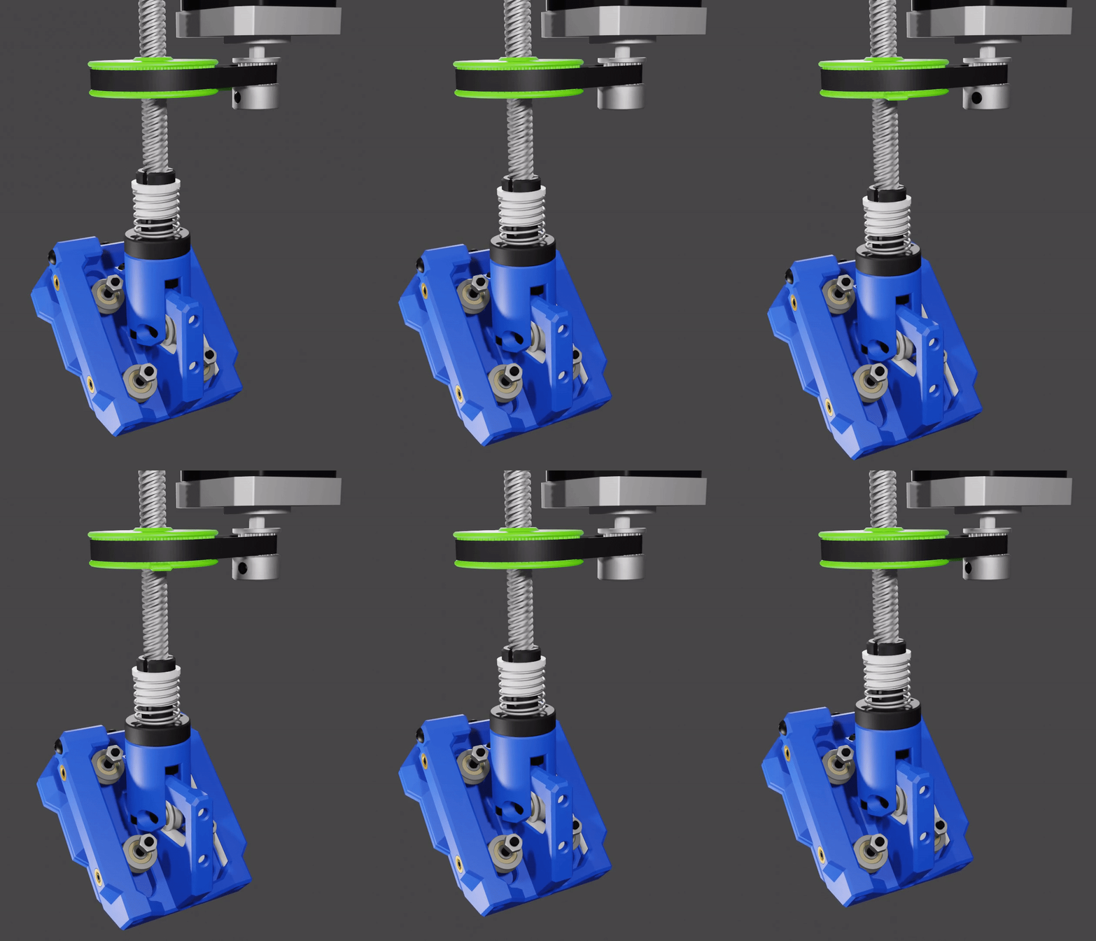
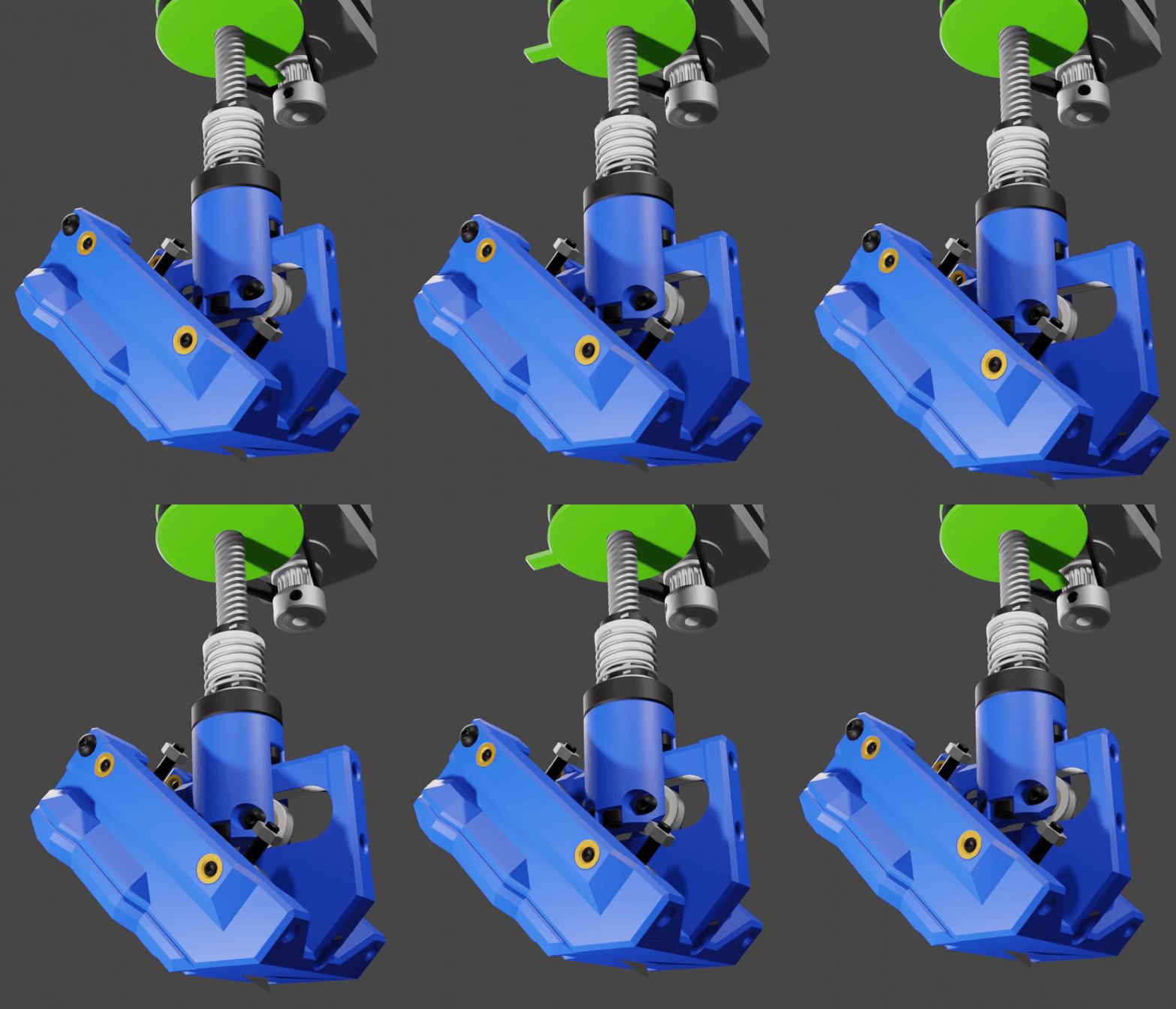
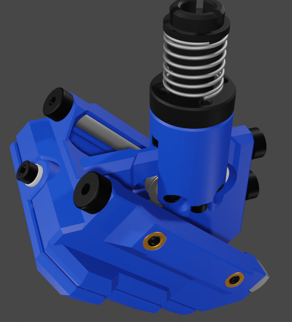
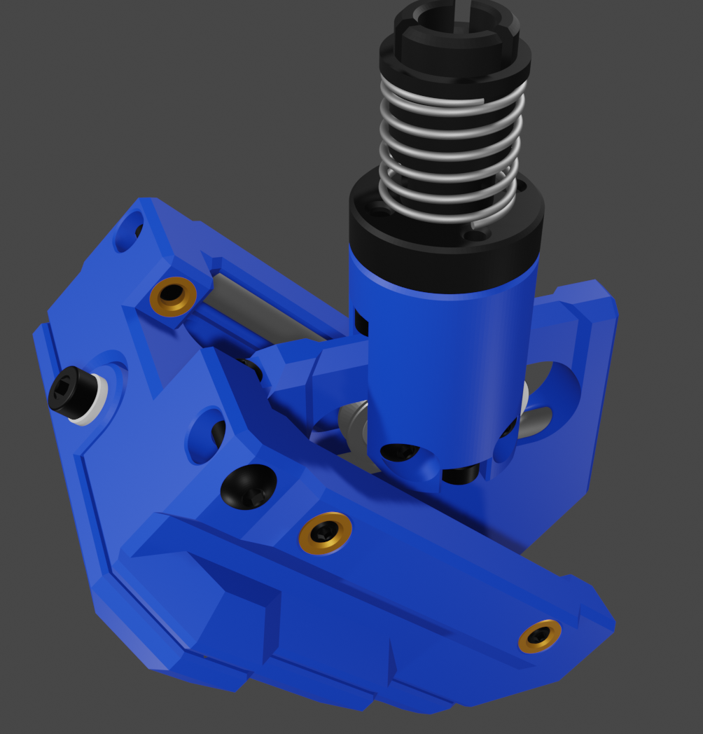 The new design uses M3 keeper screws that prevent the 5mm rods from working out of the Slider block. To allow for disassembly the keeper screw can be removed and the rods pushed out via the 3mm through holes at the end of the rail slots.
 roger_archibald
 Sam Griffen
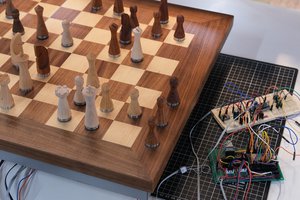
 Phantom Chessboard
 Robert Kirberich
Well I suppose that you could move the X,Y,Z axes simultaneously and achieve a plunge at a 45 degree angle to match the blade angle. That would require a much more complicated algorithm to calculate the knife path, as the X and Y coordinates on the surface of the board would (where the zero depth would be) would be a function of the plunge depth and the rotation angle of the knife holder. I will think about that, and do some calculations/simulations to see how difficult it would be to process a cut path for that kind of operation. My original idea was to create a plug in for Inkscape to output the required g-code, this would just make that a lot more interesting to code. Thanks... you have sparked off a very interesting idea.