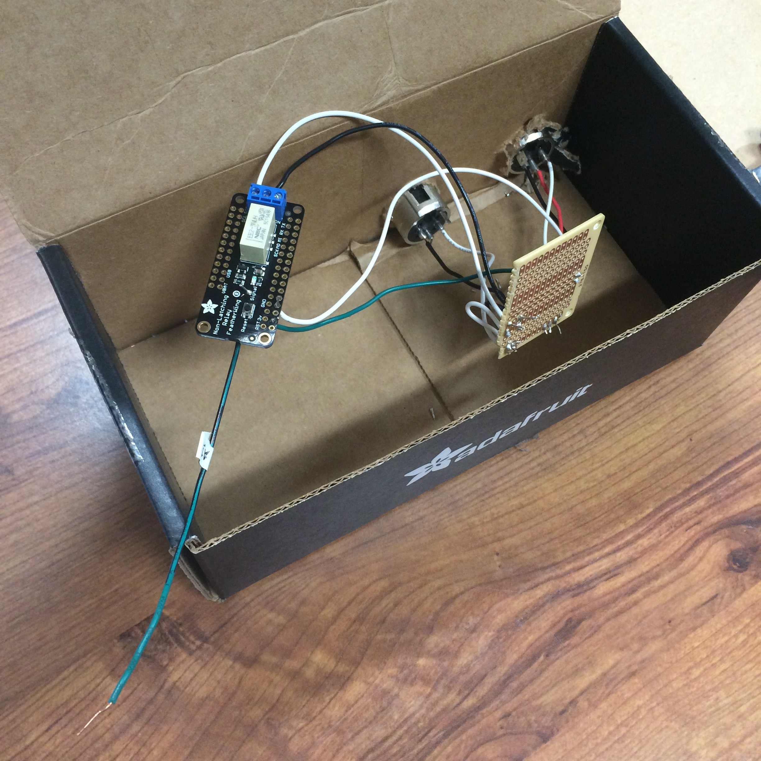
• Fabrication

    evac01/23/2017 at 18:11 0 comments

    Yesterday I spent my time soldering the components to a Radio Shack project board. Overall, I was successful. The one exception to this success was accidentally covering the 3V rail of the Feather to the ground rail of the project board. When the sensor was connected, the device acted as if the sensor was always on. While this was a setback, I am thankful that this misrouting didn't cause me to fry any of the components.

    Using the Adafruit box I received the components in, I fashioned an enclosure for the completed device. The following image is a process photo of the fabrication process. The box will live inside a rack along with the rest of the gear needed for audio playback in the venue.

  • Progress + Testing

    evac01/15/2017 at 23:28 0 comments

    Last week, I continued work on the project during a weekend that was extended due to snow.

    I started off by running the Blink sketch on the Feather board. The board proved to be similar enough to the Adafruit Trinket that I have some experience with, which was reassuring. Next, I read the documentation for Adafruit's PIR sensor, loaded the PIR test code onto the Feather, wired the sensor to the Feather with some hookup wire and a breadboard, and did a brief test. Thankfully, the VBUS pin worked fine to power the sensor. The code, which can be found here, follows:

        /*
         * PIR sensor tester
         */
         
        int ledPin = 13;                // choose the pin for the LED
        int inputPin = 2;               // choose the input pin (for PIR sensor)
        int pirState = LOW;             // we start, assuming no motion detected
        int val = 0;                    // variable for reading the pin status
         
        void setup() {
          pinMode(ledPin, OUTPUT);      // declare LED as output
          pinMode(inputPin, INPUT);     // declare sensor as input
         
          Serial.begin(9600);
        }
         
        void loop(){
          val = digitalRead(inputPin);  // read input value
          if (val == HIGH) {            // check if the input is HIGH
            digitalWrite(ledPin, HIGH);  // turn LED ON
            if (pirState == LOW) {
              // we have just turned on
              Serial.println("Motion detected!");
              // We only want to print on the output change, not state
              pirState = HIGH;
            }
          } else {
            digitalWrite(ledPin, LOW); // turn LED OFF
            if (pirState == HIGH){
              // we have just turned of
              Serial.println("Motion ended!");
              // We only want to print on the output change, not state
              pirState = LOW;
            }
          }
        }

    After fumbling around with the Arduino IDE's GUI, I was able to view the results of the program in the Serial Monitor. Everything seemed to be in order.

    I then read up on the documentation for the Relay FeatherWing. I added a wire to the Feather on pin A5, and a wire to the Signal pin of the FeatherWing. On a breadboard, I connected A5 to Signal and modified the PIR test code to switch on the relay when motion is detected. The code then read as follows:

    /*
     * PIR sensor tester
     */
     
    int ledPin = 13;                // choose the pin for the LED
    int inputPin = A0;               // choose the input pin (for PIR sensor)
    int pirState = LOW;             // we start, assuming no motion detected
    int relPin = A5;
    int val = 0;                    // variable for reading the pin status
     
    void setup() {
      pinMode(ledPin, OUTPUT);      // declare LED as output
      pinMode(inputPin, INPUT);     // declare sensor as input
      pinMode(relPin, OUTPUT);      //declare pin A5 as relay trigger
     
      Serial.begin(9600);
    }
     
    void loop(){
      val = digitalRead(inputPin);  // read input value
      if (val == HIGH) {            // check if the input is HIGH
        digitalWrite(ledPin, HIGH);  // turn LED ON
        if (pirState == LOW) {
                                   // we have just turned on
          Serial.println("Motion detected!");
          digitalWrite(relPin,HIGH);
          Serial.println("Relay on!");
          // We only want to print on the output change, not state
          pirState = HIGH;
        }
      } else {
        digitalWrite(ledPin, LOW); // turn LED OFF
        if (pirState == HIGH){
          // we have just turned of
          Serial.println("Motion ended!");
          digitalWrite(relPin,LOW);
          Serial.println("Relay off!");
          // We only want to print on the output change, not state
          pirState = LOW;
        }
      }
    }

    I checked and uploaded the code, but saw no result on the relay. After closer inspection, I realized that the relay did not have power. I returned to my soldering iron, and added a wire to 3V on the FeatherWing, and a wire to the 3V bus on the Feather. I went back and tried the sketch again. Another round of thought revealed that I hadn't connected the FeatherWing to ground. At this point, I made two notes:

    "This isn't a complete circuit. Oops"

    and

    "Solder ground to relay. Headers would have eased this process."

    Once all the necessary connections were made, the sketch worked as expected.

    Satisfied, I ended work on the project for the afternoon.

    This past Friday, I began thinking about the manner in which I would power the board and sensor when the motion sensor assembly was installed in the gallery space. My professor suggested that I could hypothetically use the MIDI out of the...

    Read more »

  • Meta-work

    evac12/24/2016 at 22:15 0 comments

    First off, a disclaimer. As with much of my work as a sound designer, the ideas I develop (or at the very least the roots of the ideas that I develop) come from external sources. When I first learned of the gallery staff's issue with sound in their space, I figured that a motion detector would fit as a solution, but didn't know what piece of gear I could use to jump from close contact to a MIDI signal. I went to my professor for help, and he suggested the MIDI Solutions F8, a piece of rack mounted gear that takes close-contact footpedal signals as input, and outputs MIDI triggers based on user specified settings.

    My professor is a big fan of the idea of "meta-work", the work one has to do in order to accomplish work. Today, when I received the components that I had specified for the triggering system, I began some meta-work of my own. Looking over the specs for the PIR sensor, I found a detail I had overlooked: the PIR needs 5V to operate. The Feather I've received operates at 3.3V.

    After looking over the pinout in hopes of a solution, I then realized that there is a VBUS pin on the Feather that I believe will supply 5V to the PIR. Based on this datasheet, I am under the impression that the current draw of the PIR is low enough to be powered from the VBUS. I think I've gotten away with this oversight... More to come as I breadboard the circuit.