 Ted Yapo
I'm going to document the various aspects of this project in build logs - even though it's already complete, this is a convenient way to organize the documentation. I recently made one of these as a gift, and thought it would be the perfect time to get all the information in one place.
All of the source code and design files for this project are in the GitHub repo. If you just want to build one, you can go there first and get what you need.
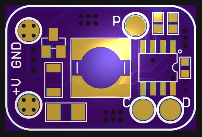
The PCBs are available for order from OSH Park. Cost is $3.05 for 3 copies. You can use these for other efficient/low-power flashlight builds, too.
I've created a detailed bill-of-materials along with links and DigiKey part numbers when appropriate - it's in a text file in the repo, and also in the first build log.
The build logs cover the following aspects of the design:
Going forward
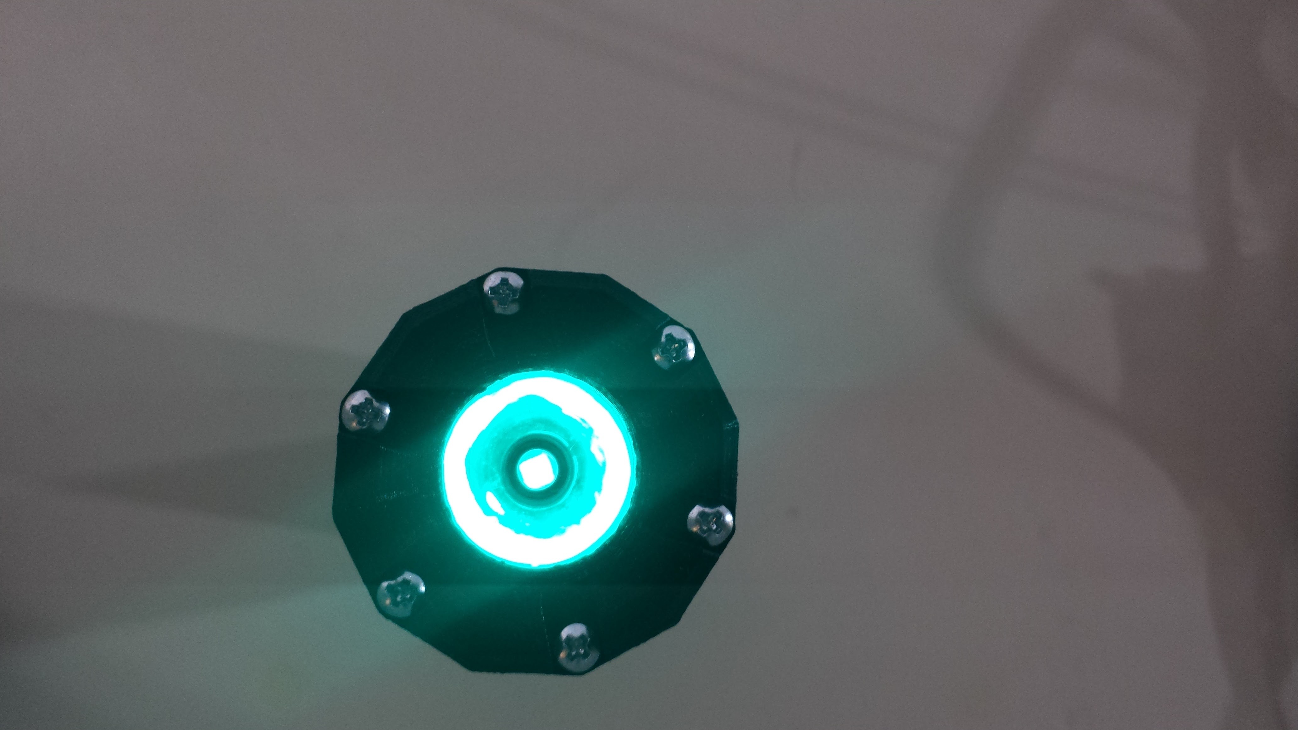
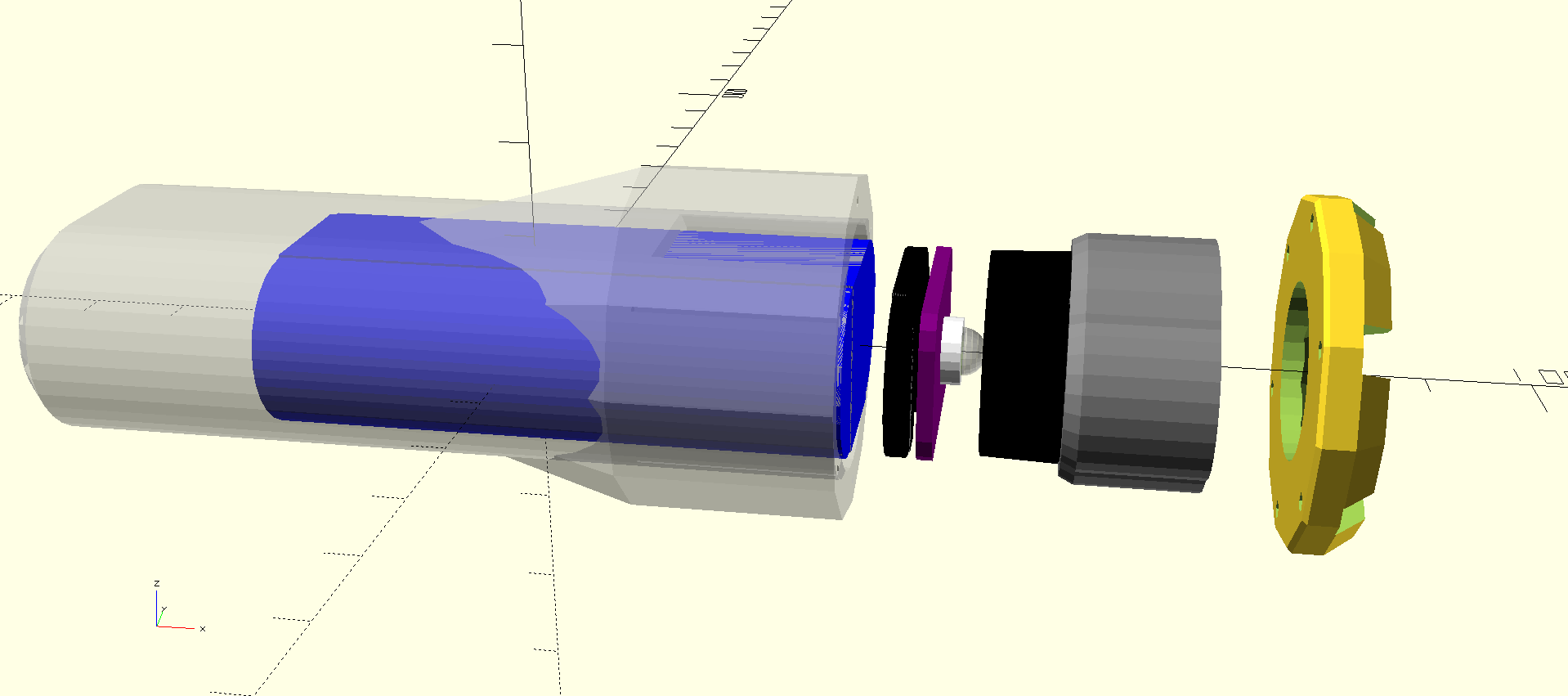
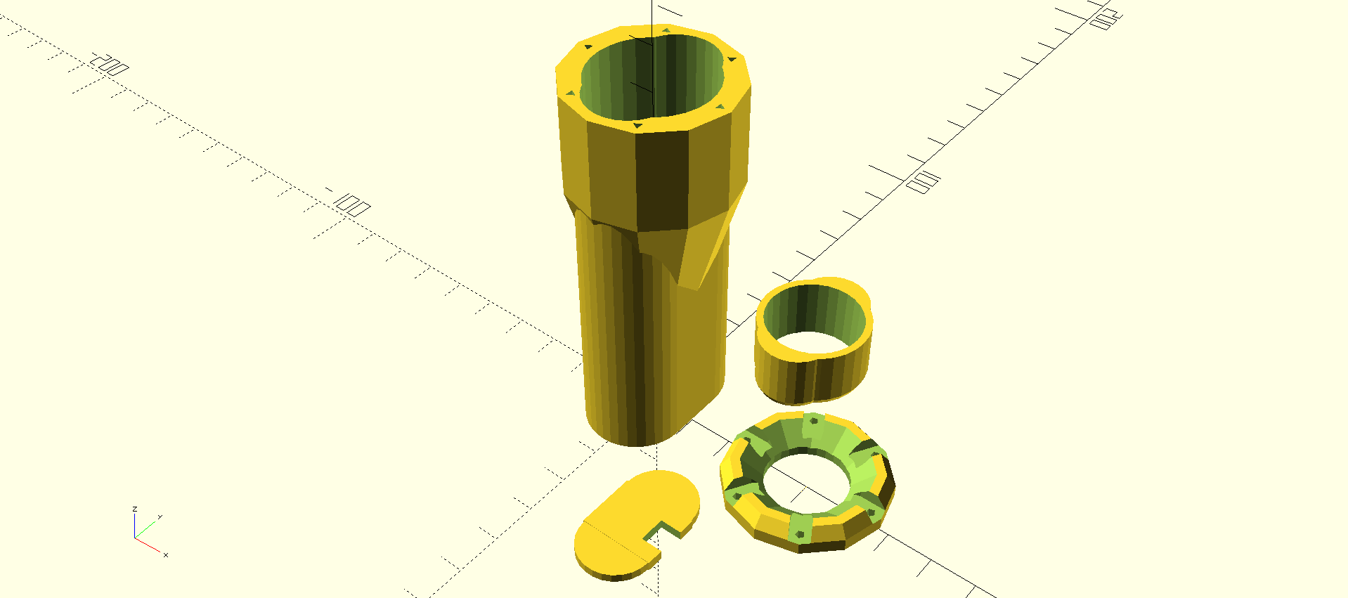
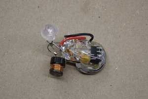
I designed the crenelated bezel on the front of the light to allow some light leakage when the unit is standing upright on its face, but due to the tight beam created by the lens, not enough light emerges to find it easily in the dark. I'm considering a printed base which would channel more of the light outward to make it visible, while making the light more stable standing up - it's easy to knock over in the dark. I'm considering an aluminum-foil reflector or fiber-optic light guides. I'll probably experiment with both. If I come up with something useful, I'll post it here.


 Elliot Williams
 piotrb5e3
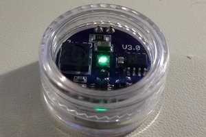

 Christoph Tack
Can these run on more than 3V without issues? It appears all the parts are rated to at least 5V, but I'm wondering if current drain would go much higher. Could these for instance be powered by a 4.2V LiPo?