 Ted Yapo
Here's the circuit used to drive the LED. A PIC12LF1571 periodically wakes to pulse the gate of an N-channel MOSFET. The MOSFET allows current to build through a 1 mH inductor; once the MOSFET shuts off, the inductor discharges through the LED to create the light pulse. There are more details about this circuit in #TritiLED.
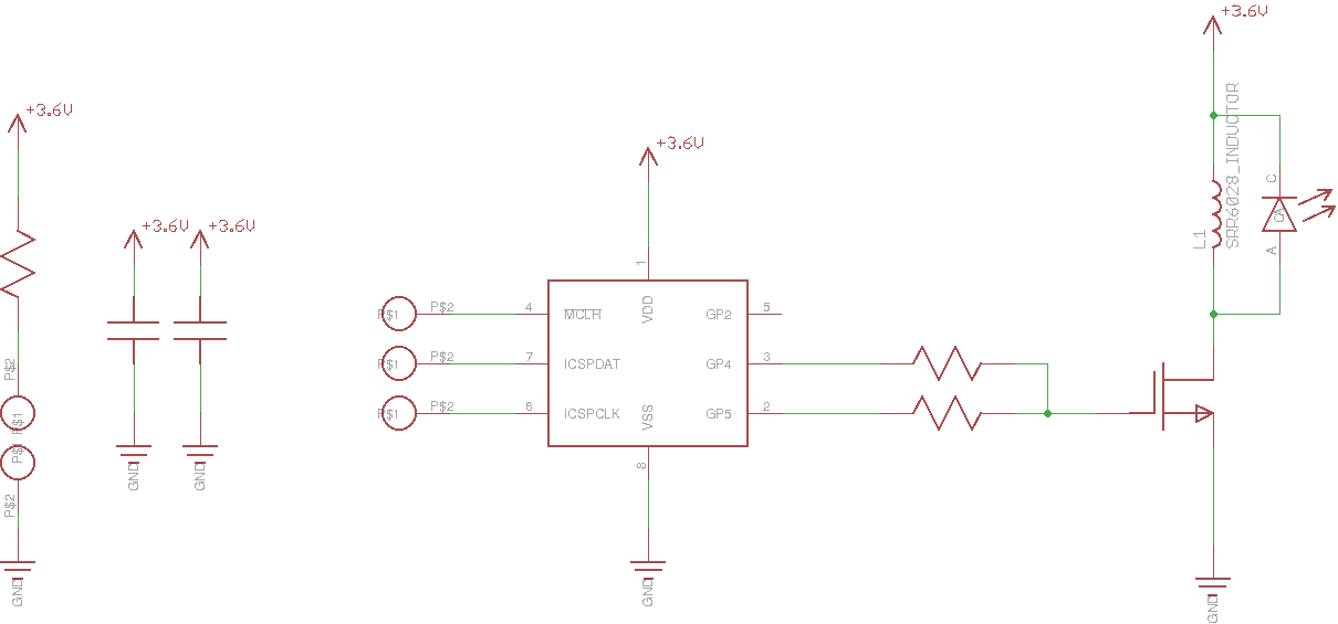
A 100-ohm resistor is added in series with the battery for fault protection - if the PIC becomes stuck for some reason, the MOSFET shorting the inductor across the supply might drain the battery, but the 100-ohm resistor will hold the current and dissipation to a safe level. Likewise, the two resistors in the gate drive circuit (22 ohm each) keep the PIC outputs from "fighting" if the software is somehow corrupted and the two outputs assume different states.
Optimal Current Drive
I measured the relative efficiency of the Chanzon 3W (45x45 mil chip) cyan LED with the #Automated LED/Laser Diode Analysis and Modeling system. Here's the efficiency for DC drive conditions:
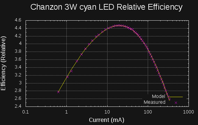
If you were driving this LED with DC, you would see peak efficiency at around 20 mA. For the flashlight design, the average battery drain is about 40 uA. At this DC current, the efficiency of the LED is abysmal, so it is much better to drive with higher-current pulses at a low duty cycle. Since the circuit shown above uses roughly triangular-shaped pulses, I wrote some code to analyze the efficiency based on the peak current in a sawtooth waveform:
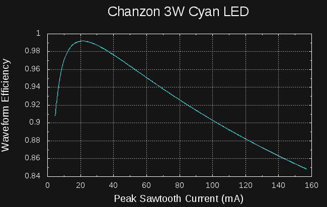
You can see that driving this LED with a sawtooth waveform of anywhere between 10 and 35 mA will achieve at least 98% of the LEDs peak efficiency. Depending on the particular inductor (the part I'm using has a 30% tolerance), the actual current will vary, but should always be in this range. More details about this analysis can be found in #TritiLED.
The software is tuned to produce an average current drain of about 40 uA at 3.6V. Lightly loaded, the lithium AA batteries will maintain about 3.6 V for most of their life. Based on a 3500 mAh capacity, a 40 uA drain will deplete the batteries in a little over 10 years. Since the battery voltage will drop somewhat at the end, resulting in a reduced current drain, you might get a little longer than this (at reduced brightness). These lithium AA's have a shelf-life of 20 years, so self-discharge over the decade of use will not be an issue.
The code blinks the LED six times every 16 ms, so over a 10-year span, the LED will blink about 118 billion times. Your heart will beat about three billion times total - unless you can come up with the coolest hack ever :-)
Bill of Materials
A more detailed BOM is in the GitHub repo, but here are the electrical/optical components listed out
- (1) PIC12LF1571 8-SOIC DigiKey part # PIC12LF1571-I/SN-ND $0.57 each
- (1) Bourns SRR6028-102Y 1mH inductor. DigiKey part # SRR6028-102YCT-ND $0.68 each
- (1) 10uF 25V 1206 X7R MLCC capacitor. DigiKey part # 1276-1804-1-ND $0.24 each
- (1) 0.1uF 25V 0805 X7R MLCC capacitor. DigiKey part #311-1141-1-ND $0.10 each
- (1) 100 ohm 1206 resistor. DigiKey part # 311-100FRCT-ND $0.10 each
- (2) 22 ohm 0805 resistor. DigiKey part # 311-22.0CRCT-ND $0.10 each
- (1) ZXMN3B01FTA N-channel SOT23 MOSFET. DigiKey part # ZXMN3B01FCT-ND $0.52 each
- (1) AA Battery holder w/leads. Digikey part # BC22AAW-ND $0.99 each
- (1) CHANZON 3W Cyan LED. Find them on Amazon : $9.52/10, AliExpress : $7.90/10, or Ebay (various sellers/prices)
- (2) Energizer L91 AA Ultimate Lithium cells. DigiKey Part # N602-ND $3.61 each.
Much cheaper elsewhere. For example, you can get 8 of them for $12 on Amazon. - (1) Lens for the 3W LED. Again, you can find these on AliExpress, Amazon, or Ebay. They will fit 1W, 3W, or 5W LEDs. Here's an example listing for them on Ebay. I have an assortment of different ones - I liked the beam from 20 and 30-degree lenses best, but ended up with the 20-degree one since it has a bright inner beam surrounded by a wider, less bright cone. I'll have to take some pictures of it.
I didn't add it all up, but if you build more than one of them, it's obviously much cheaper. The 0805 resistors, for example, are $0.10 for one, but $0.19 for 10. Since you probably need to buy 10 of the LEDs and lenses anyway, you might as well build a bunch and save. I guess this is where kits or group buys bring the price down :-)
PCB Design
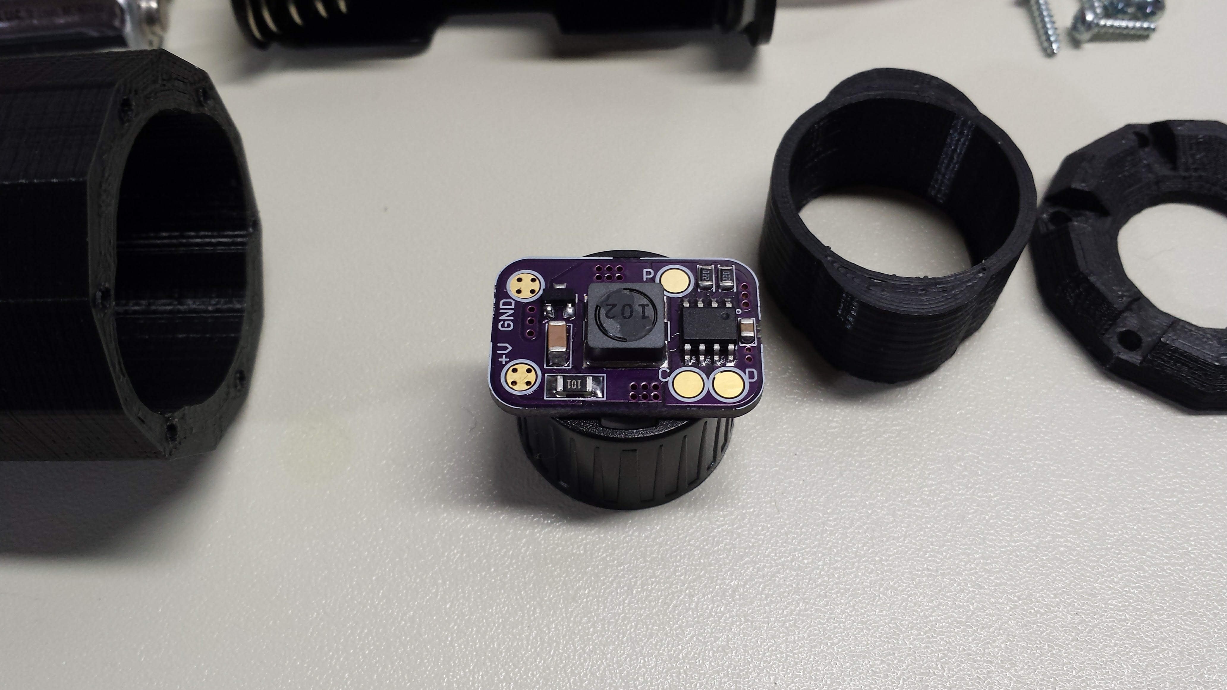
Here are the PCB's front and back. All the components except the LED mount on the back of the board - they can be reflow soldered, then the LED can be hand-soldered on the front.

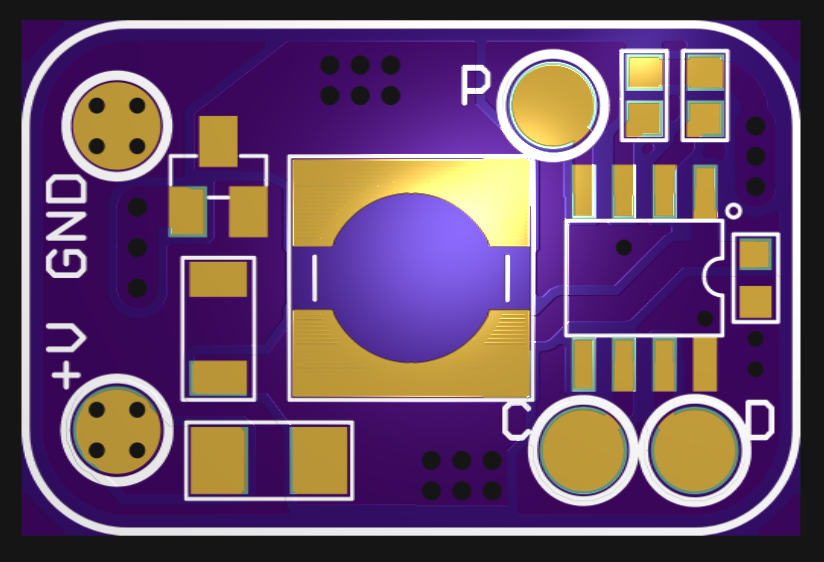
The boards can be ordered from OSH Park. Cost is $3.05 for 3 boards. The gerber previewing software I use doesn't round the corners on these renderings, but as you can see below, the board fab will. The battery connections are intended to be soldered to the +V and GND pads. Vias are provided in the pads for strain relief, preventing the pads from lifting off the boards with the wires. Pads are also provided for ICSP programming of the PIC. Here's the key to my terse labeling:
- P: MCLR/VPP
- D: ICSPDAT
- C: ICSPCLK
I didn't make a pogo-pin jig for this board. You can temporarily solder wires to the programming pads if necessary - more details in the assembly log.
The board is held in place by the LED package. The lens for the LED is designed to press-fit onto the LED itself. This holds the board in place the flashlight:
Discussions
Become a Hackaday.io Member
Create an account to leave a comment. Already have an account? Log In.
Is the assembled board available for sale? I'm interested in trying out 2 of these.
Are you sure? yes | no
No, I am not selling the boards assembled at this time.
Are you sure? yes | no