I am designing kinetic sculptures of robotic bugs and I have been determined to use oscillating patterns which are sinusoidal in shape. The goal for this project was to create wave forms to control flapping wings like a butterfly's. Additionally, I'd love for as much of the electronics as possible to be analog, to match the analog quality of the natural organism in reference. However, the cheap price and availability of digital hobby radio control electronics means there is a strong practical incentive to use digital workflows. Therefore, I created this hybrid analog and digital system which will generate the control signals in the analog domain, and hack into the ADC side of a Fly Sky R.C. Tx.
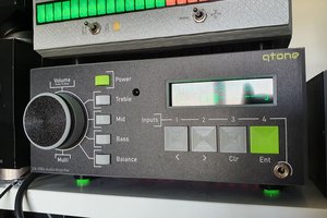
Upon learning about the revival of analog computing, I read Bernd Ulmann's book Analog And Hybrid Computer Programming. This helped me develop a simple op-amp sine wave generator using integration and feedback. I also researched and borrowed a lot of circuits from DIY analog synth projects. Two op-amp integrators and a comparator feedback on themselves to generate a sine wave. The frequency is determined by the capacitor values of the integrators. That sine wave is then copied and inverted to form a left and right signal. The amplitude is controlled with an operational transconductance amplifier (OTA) in a voltage controlled amplifier configuration. The resulting sine wave's center points are then adjusted with summing amplifiers. Finally, each left and right sine wave is copied and phase shifted, creating four sine wave signals, two pairs with slight phase shift. Luckily it was pretty easy to interrupt the control signal path of the R.C. Tx and inject these sine wave signals into the existing ADCs of the remote. All I had to do was cut the wires to the built in joystick gimbals and use those as my control inputs on my analog board. Then, the output signals were setup in the same expected voltage range of those joystick potentiometers, so the transmitter doesn't "know" the difference. The result is that the transmitter can still be used in the same way, but it transmits the oscillating servo signals directly.

The transmitter has a battery compartment for enough AAs to create 12V. I used two power supply modules from Pololu to generate 5V and -5V. The LM13700 and LM324 each operate best with at least 9V difference on their input power, so these power supplies are the bare minimum voltage levels one should use. The MCP6004 op-amps are rail to rail and max out at ~5V, which was enough to cover the expected 0-3.3V control voltage in the transmitter. The entire board draws about 30mA of current.
I designed the PCB in KiCad and ordered them from OSH Park. The components came from DigiKey and I ordered enough to build all three PCBs, but with different oscillator frequencies. I hand soldered the SMD components, slowly.

 Wassim
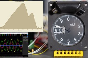
 smartroad
 ensafatef
Clever idea, great execution!