 joey castillo
One of the joys of setting this up in Adafruit's Feather ecosystem is that there's a standardized board style for add-ons and breakouts: the FeatherWing. It's like, sure, I could solder to the Feather headers, or even plug into socket header in a wing doubler or tripler. But if, say, I wanted to turn this Feather Op Amp Lab into a microphone amplifier? I could just design a wing that connects the relevant op amp pins to a 1/8" jack, with all the necessary passives right there on the board.
I'm not quite there yet; for the moment, I mostly want to make with the prototyping. But keeping track of which pins are which is a drag; once I decided to put the analog reference pin on AREF and the DACs on A0 and A1, the ordering of the Op Amp pins became a mess:
- OPAMP0_NEG is A0
- OPAMP0_POS is A4
- OPAMP0_OUT is A5
- OAPMP1_POS is A3
- OPAMP1_OUT is A2
- OPAMP2_POS is A1
- OPAMP2_OUT is AREF
Yeah. It's not satisfying at all. What I really want is to have all my op amp pins in a row, arranged in an order that mostly makes sense. So I made a FeatherWing.
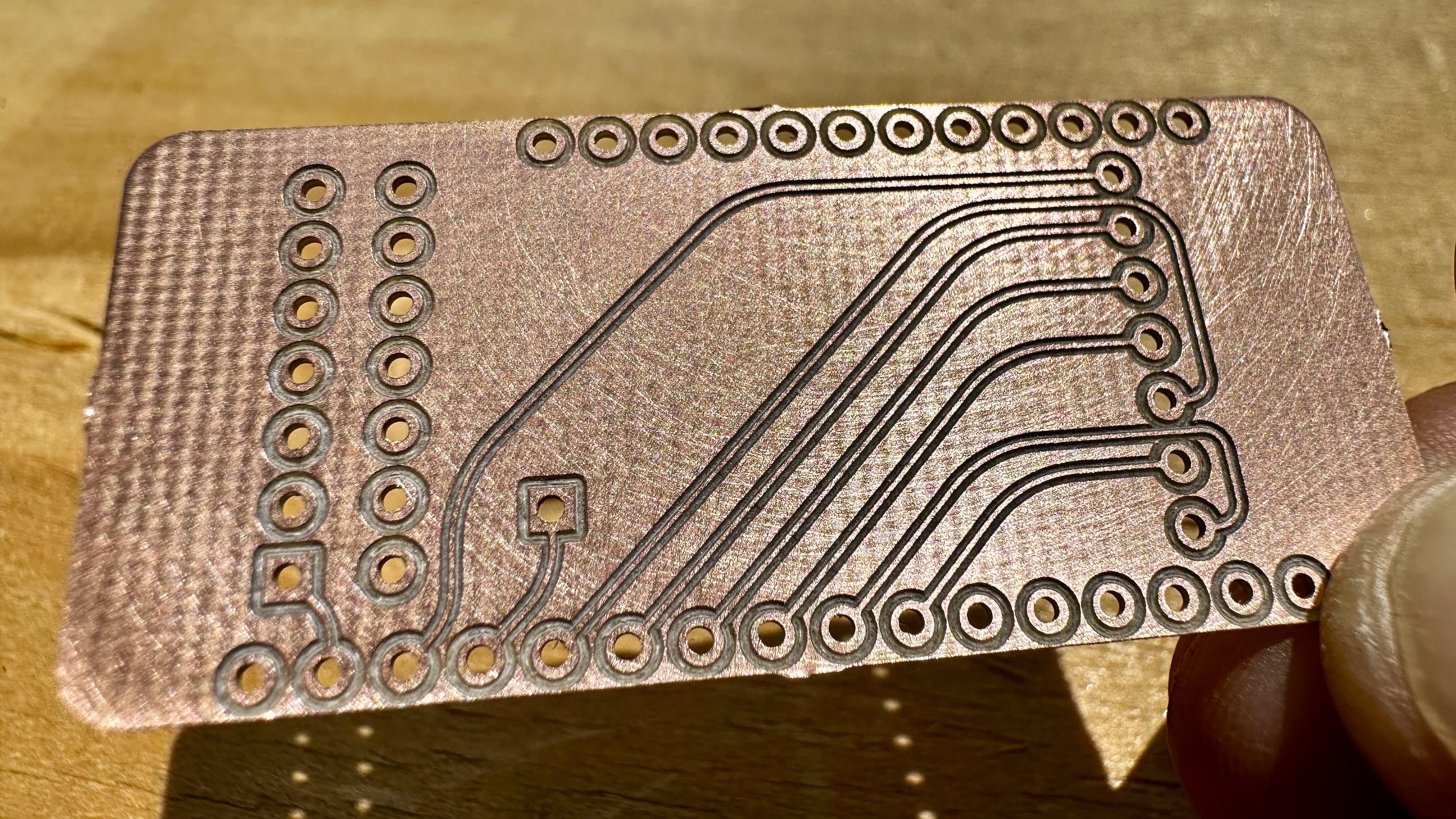
This FeatherWing is fairly simple: it gives me a row of power and ground pins on the left, and breaks out the analog row on pins on the right. I milled it here at the lab, which is a fascinating process of its own; you start with a piece of copper clad fiberglass, and the PCB mill uses a 0.2 mm bit to carve tiny grooves in the surface — just deep enough to cut through the copper and isolate pads and traces. It looks something like this:
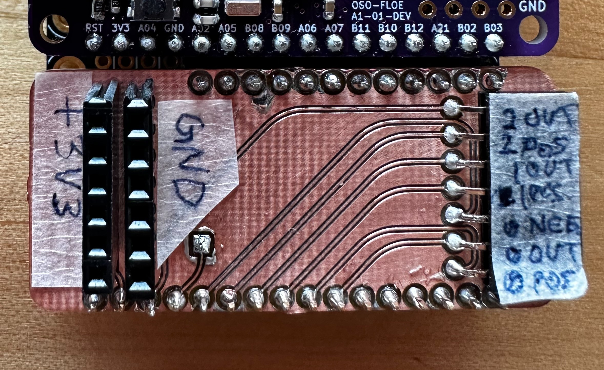
Once soldered together and labeled, it looks something more like this:
This wing has taken me through the first experiments with the Feather Op Amp Lab. It makes it super easy to hook the outputs up to an oscilloscope, or to connect the inputs to a breadboard and the maze of passives I need to use to condition analog signals. But really, the first tests are just to make sure that the gadget is doing what it's supposed to do, and this involves building some very simple op amp circuits that don't even need any external components.
Below is a simple comparator circuit (focus on OPAMP1, in the middle of that diagram in the OLED). I have the SAM L21's DAC configured to output a 100 Hz sine wave, and I've routed its output to OPAMP1's inverting input. The non-inverting input goes to the resistor ladder at the bottom, currently configured to deliver a voltage 1/2 of VCC. This essentially turns our analog sine wave into a square wave, whose duty cycle is dependent on the ratio of R1 and R2 in the associated resistor ladder.

It's a very simple op amp circuit, to be sure. But it shows the Feather Op Amp Lab working, and it shows that we can build a fully analog circuit using no more silicon than the SAM L21 microcontroller itself. Pretty cool!
Discussions
Become a Hackaday.io Member
Create an account to leave a comment. Already have an account? Log In.