 joey castillo
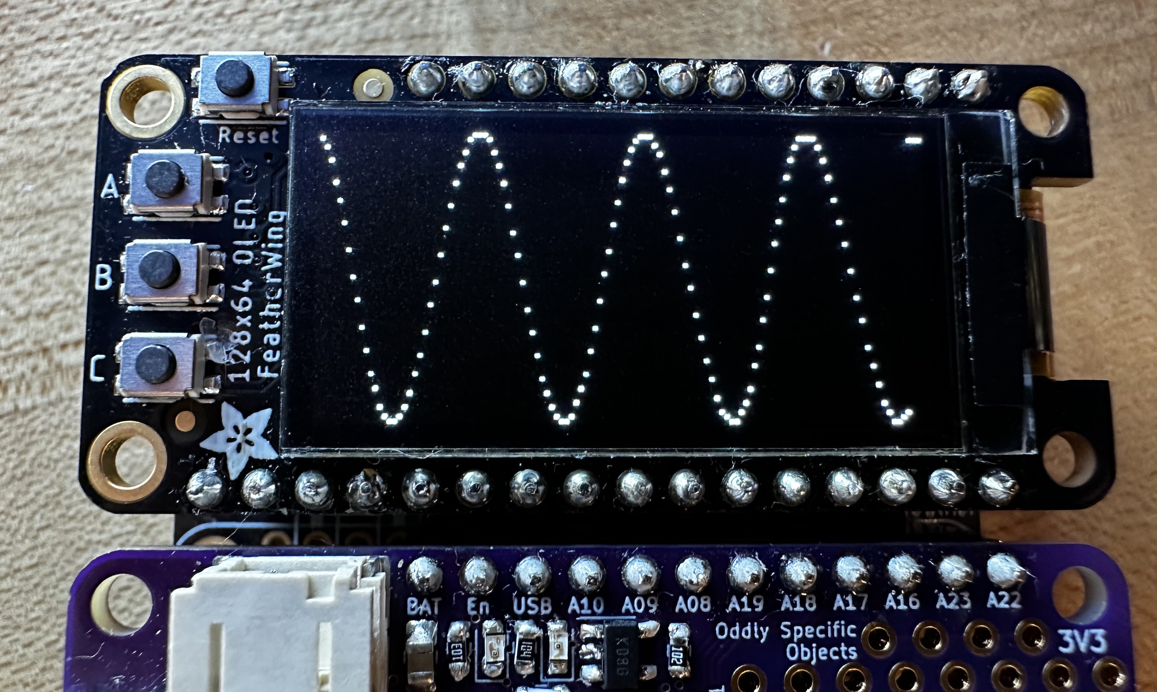
This update works best if you just understand visually what's going on here. I've set up the DAC on my SAM L21 Feather to feed into the first internal op amp. The DAC is outputting a 1 Hz square wave, and I've configured OPAMP0 as a voltage follower, so the output just follows the input. Up until now, I would have had to plug wires into the oscilloscope to visualize the analog waveform coming out of OPAMP0. But then of course, there's already an ADC inside this microcontroller. And a display. So yeah, TL;DR:
This is cool and all, but then it's not showing us anything we didn't know: if we output a level of 2 volts on the DAC, and OPAMP0 is a voltage follower, and we're measuring the output with an ADC, we're not really doing anything that interesting. We could have just plotted the value we wrote out, right?
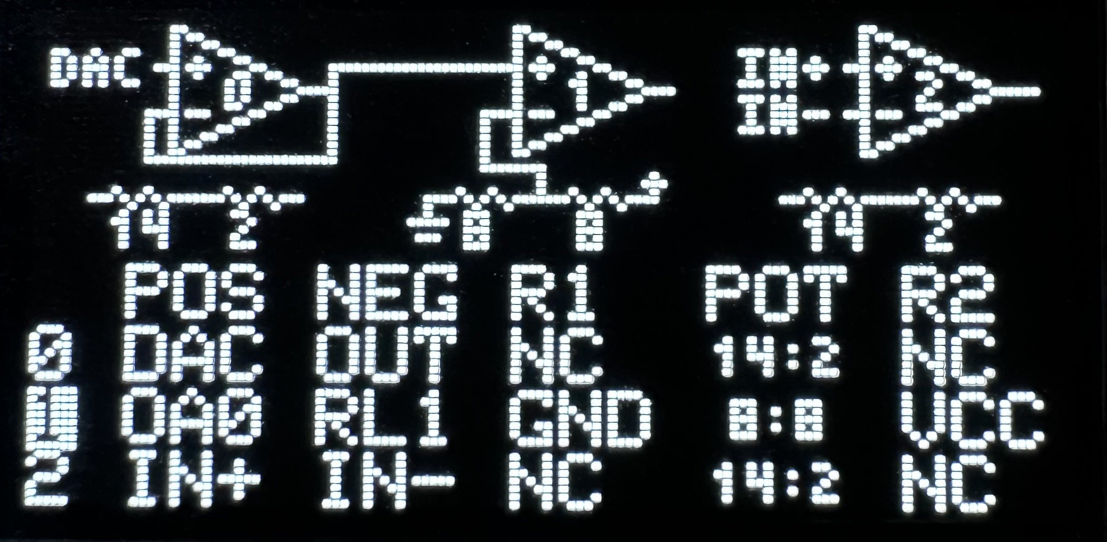
To explore the possibilities of the Feather Op Amp Lab, let's configure OPAMP1 to do something with this sine wave. It's the same comparator circuit from last week: OPAMP0 buffers the DAC output, then we put that output on OPAMP1's positive input. The negative input goes to the resistor ladder, in this case configured to divide VCC in half.
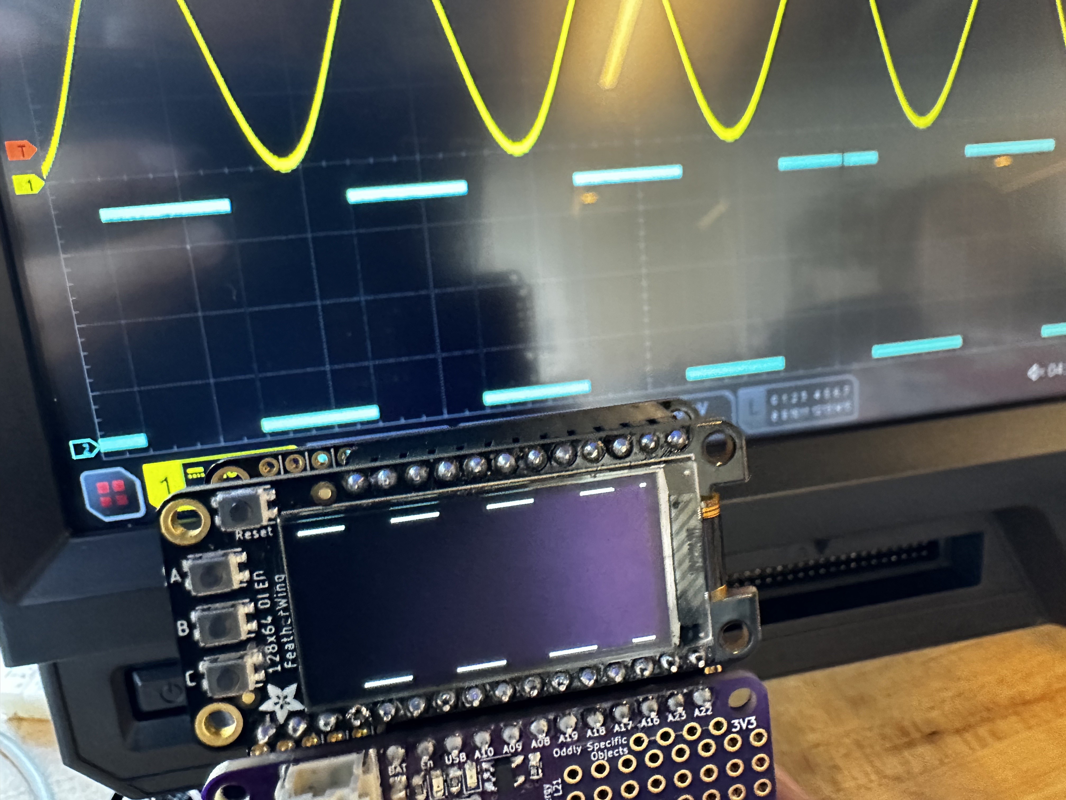
This setup should turn our sine wave into a square wave with a 50% duty cycle. And sure, last week we visualized this on the oscilloscope. But with this week's addition, all we have to do is hold down on button B, and we can see the square wave output right there on the Feather Op Amp Lab's OLED — no external parts required!
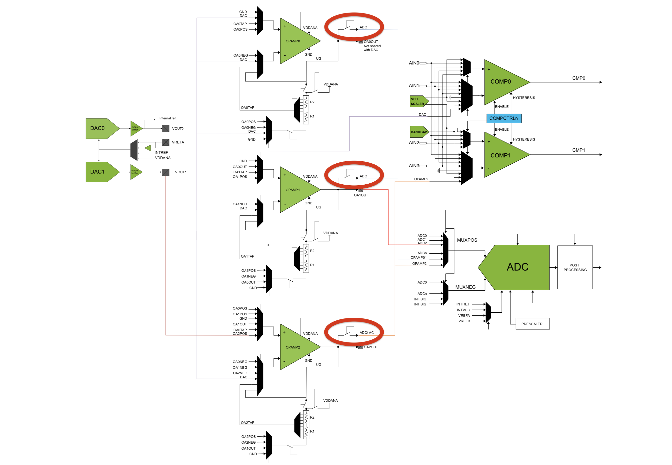
The core of this feature is in one flag that we're able to set in each OPAMP's control register. Called ANAOUT, it controls an internal switch that either connects or disconnects the op amp's analog output to the ADC peripherals inside the microcontroller. It's depicted in a block diagram in the data sheet, titled “Interconnections of Analog Signal Components”:
In the end, it was a one-line function to add this feature to my op amp driver:
void opamp_set_analog_connection(uint16_t instance, bool connected) {
    OPAMP->OPAMPCTRL[instance].bit.ANAOUT = connected;
}
Again, it feels very simple looking and basic with just this simple comparator circuit, but I think the possibilities at play here are really exciting!
Discussions
Become a Hackaday.io Member
Create an account to leave a comment. Already have an account? Log In.