Key features are as follows:
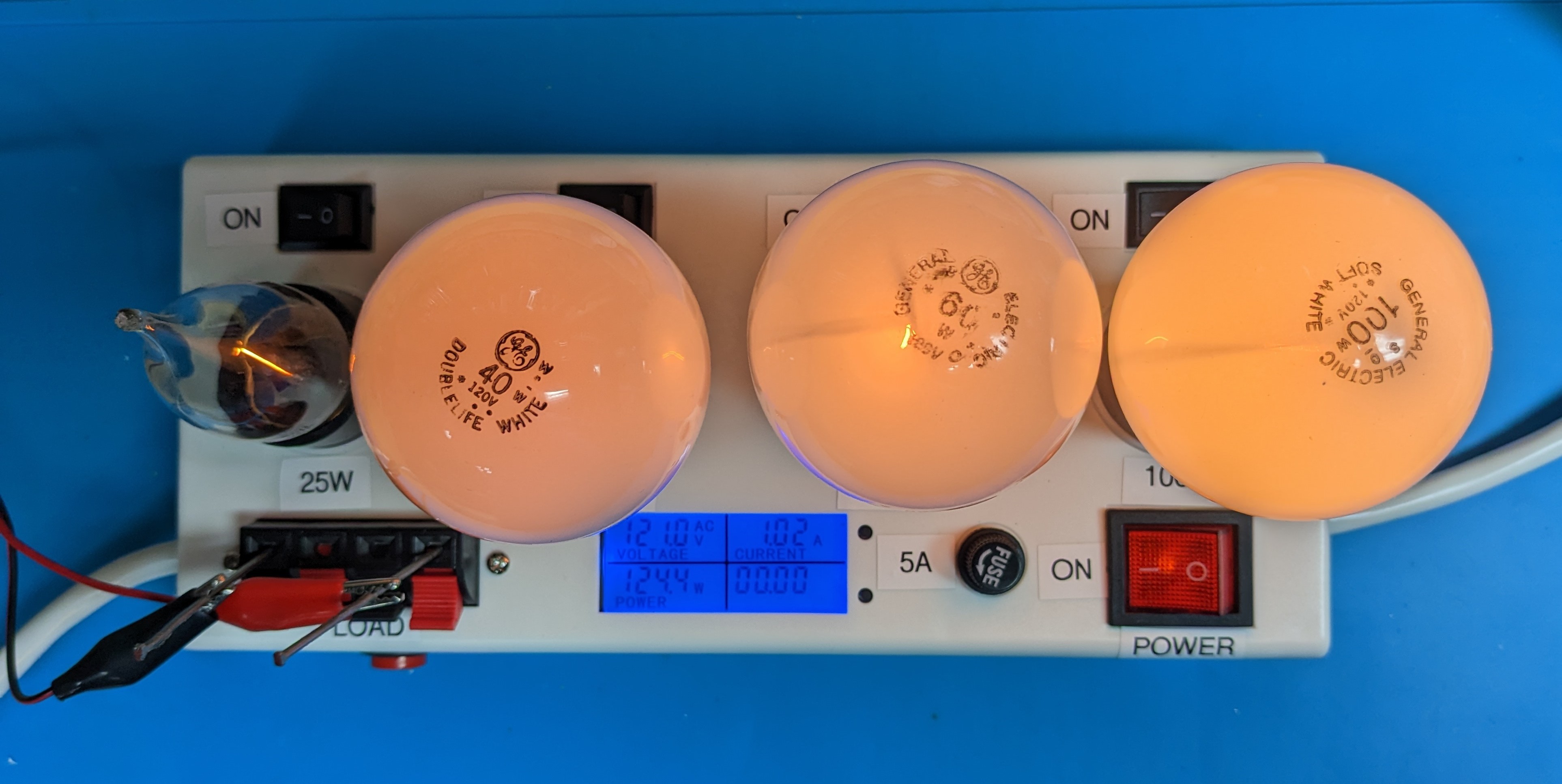
- The 4 switched bulb sockets allow you to include a geometric series of common bulb wattages (I use 25W, 40W, 60W, 100W) wired in parallel to give a range of current limits (in my case on 110v from about 225mA with just the 25W bulb switched on to about 1.5A with all four bulbs switched on) - choose your bulb wattages to meet your range of current needs
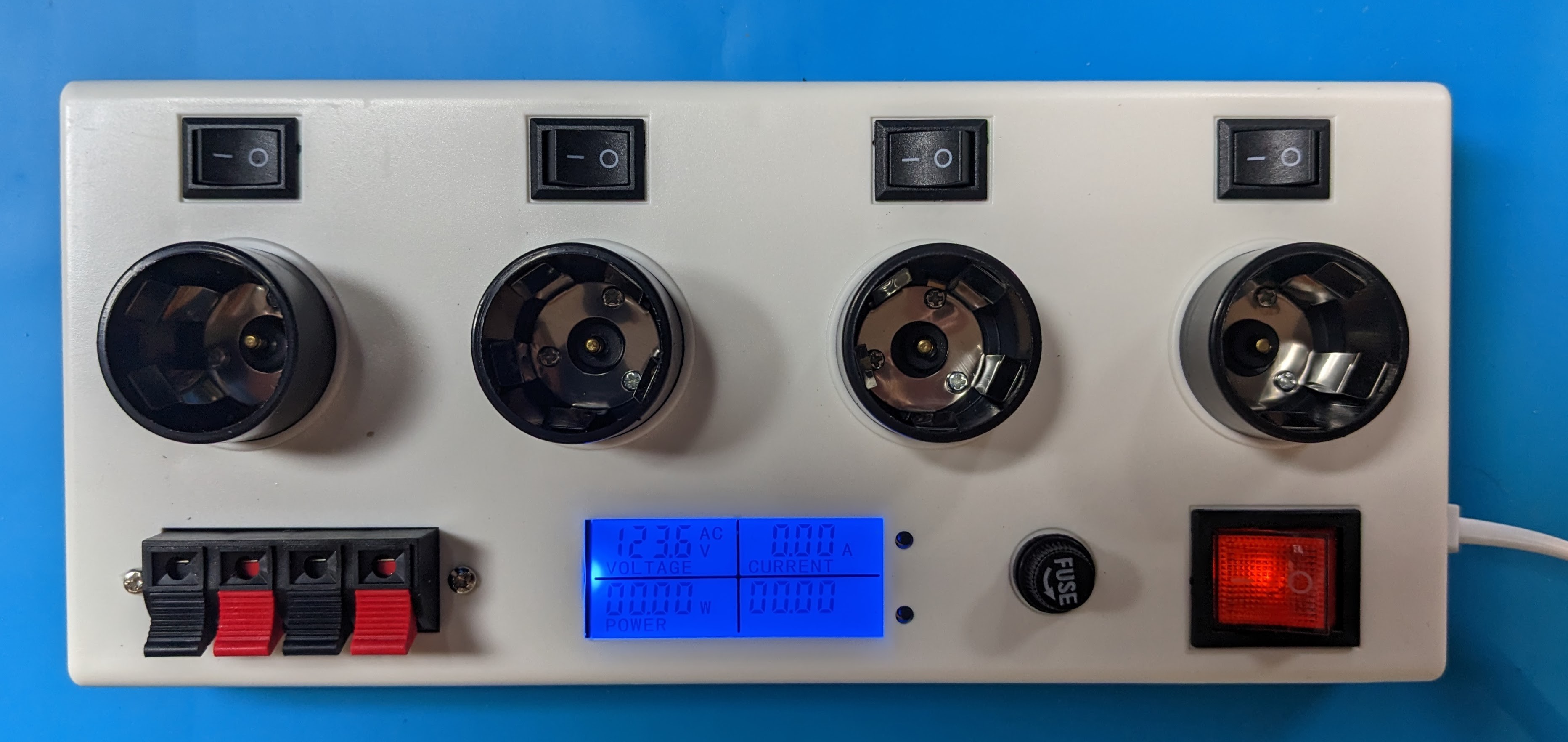
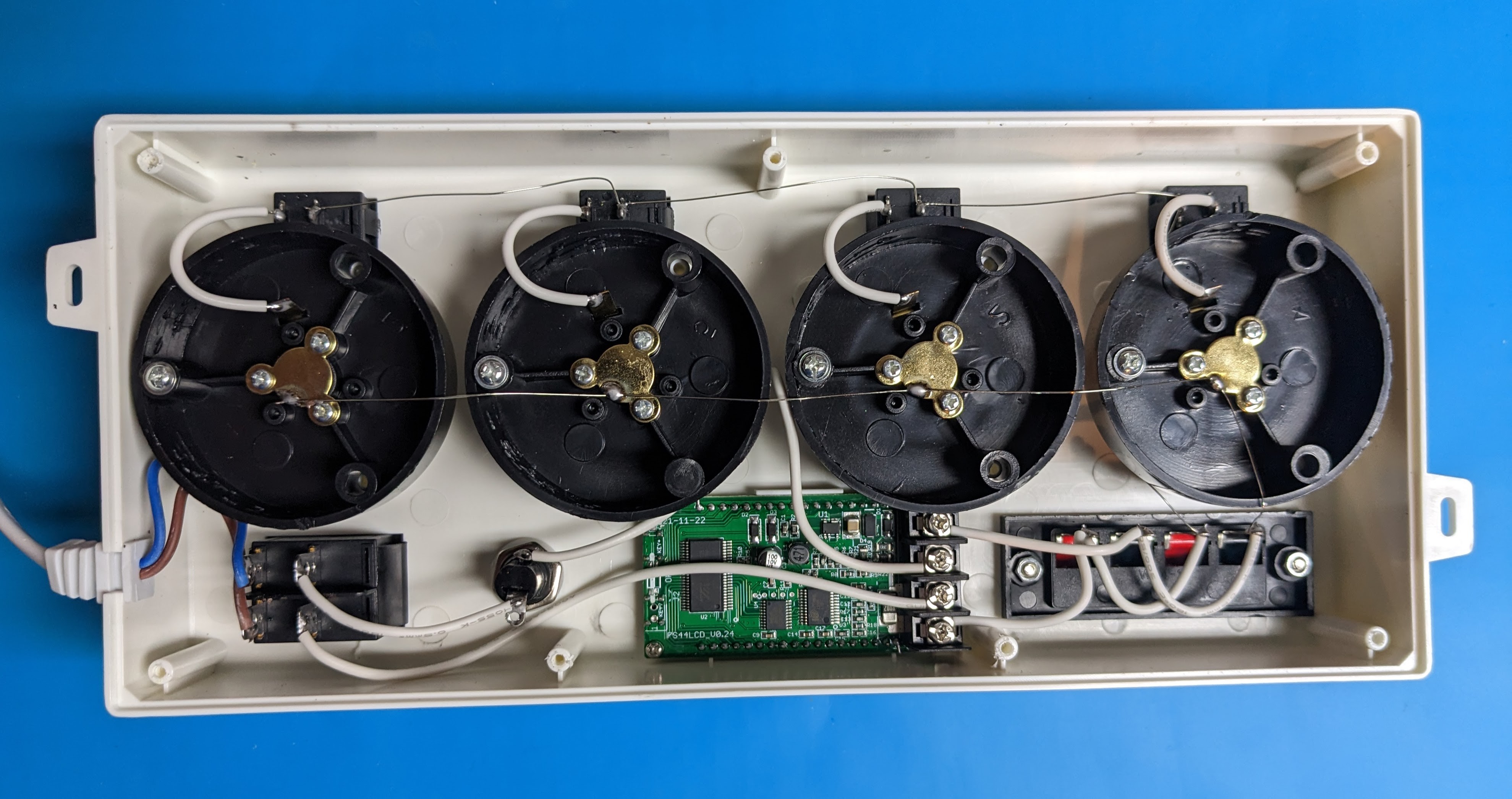
- The existing lighted (indicator) power switch is SPDT so that it safely disconnects both hot and neutral. Also there is a 5A fuse in series.
- The dual wiring block (originally wired parallel to the bulbs but converted to be in series ) allows you to connect the load to the wiring block with the magic of current-limiting provided by the non-linear resistance of the bulb filaments
- You can (optionally) add a standard AC socket (in parallel to the wiring block) to plug in a standard AC-corded device -- I chose also to replace the 2-wire original power cord with a grounded power cord that then allowed me to pass through the ground to yield a grounded socket.
- The (optionally) added pushbutton "test" button is also wired in parallel to the load (i.e., wiring block and AC socket) allowing you to momentarily test/confirm which bulbs are switched on and to confirm that the circuit is working by "short-circuiting" the load
- The power meter shows the input voltage, current, power, and power-on time
- Optionally, one can add an additional voltage AC voltage meter to show the voltage across the load rather than just the input voltage (or you can rewire the existing meter to go across the load -- however, then the meter will cut out when the bulbs light and the load voltage drops below about 40V)
To use:
- Determine which bulbs to switch on base don desired maximum current
- Turn on the power-switch when ready
- Optionally, use the test-button to verify max current flow
- Connect load to either wiring block or optional AC socket
- Monitor current and power using the meter
 Stefan Wagner
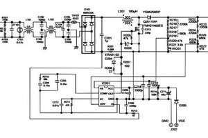
 engineerkid1
 w_k_fay
 John Loeffler