 Vijay
Vijay
HackadayPrize Video:
Table of Contents:
| Subsystem | Links to Log/Document |
| Mechanical Development & Testing | • 1st 3D Printed Prototypes • 3D Printing: The Devil is in the Details • Assembly and Single dot test • Two dot test • Single Dot Test on PCB • 12th time is the charm |
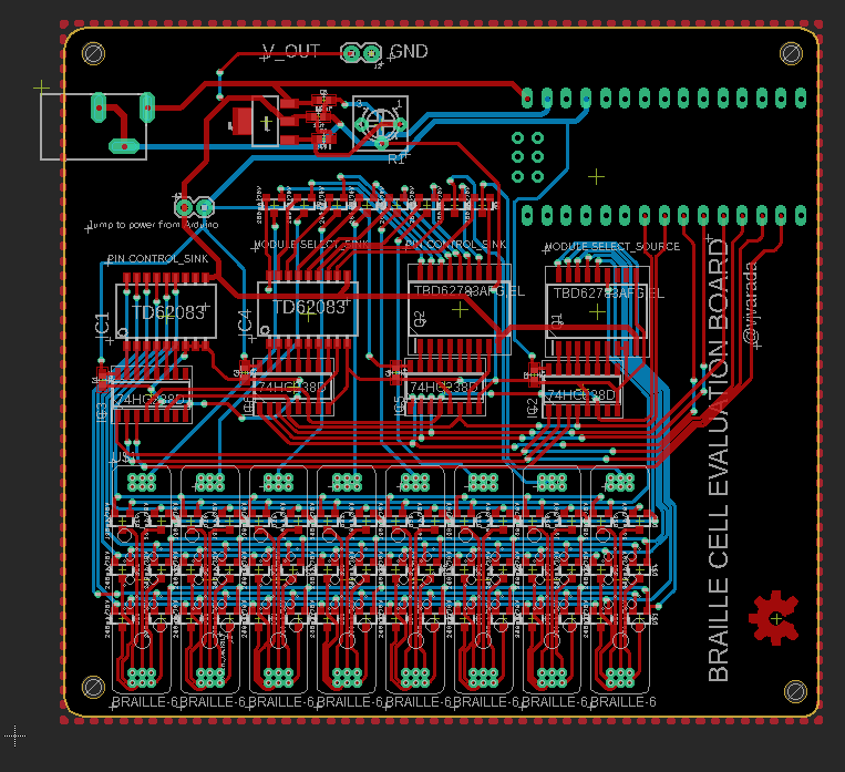
| Electronics/Firmware Development & Testing | • Braille Cell Array Drive Circuit • Updated Drive Electronics • PCB Design of Braille Cell Evaluation Board • Braille-Module & Driver PCB's • Testing Electronics • Single Dot Test on PCB |
| Solenoid-Coil Winding Tool | • Coil Winding Tool for Micro-Electromagnets • Updated Winding Jig for Ferrite Cores vs Steel Cores |
| Technical Documents | • References & Previous Work • BOM & Cost • CAD Design • PCB Source Files |
Working Principle:
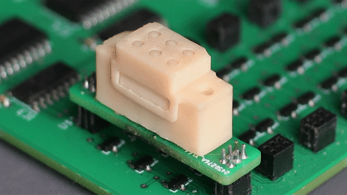
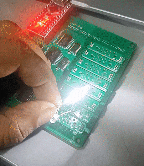
Fig. 1 Braille Cell Actuation Test
This is a 3D Printed, electromagnet-based braille display module that can represent braille characters.
The key working principle is a cam actuator, consisting of an eccentric cam that has a rare-earth magnet embedded into it which is rotated to two stable positions by the action of an electromagnetic that changes its polarity. The rotation of the eccentric cam causes a braille dot to be lifted up or taken down.
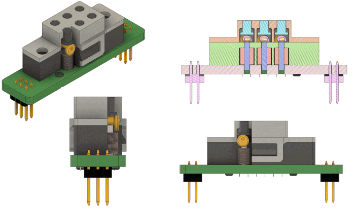
Fig. 2 Braille Cell Working Principle
Once the Braille pin is lifted, and the cam rotates to its stable position, the weight of a finger on the pin (while reading braille) cannot back drive the cam. This not only satisfies the need for protrusion force of the braille pin but also that the electromagnet need not be powered once the pin has been lifted resulting in lower power consumption.
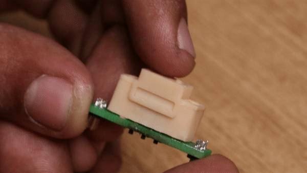
Fig. 3 Protruding Force Test
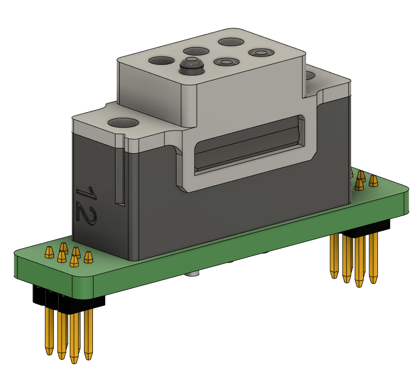
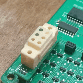
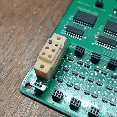
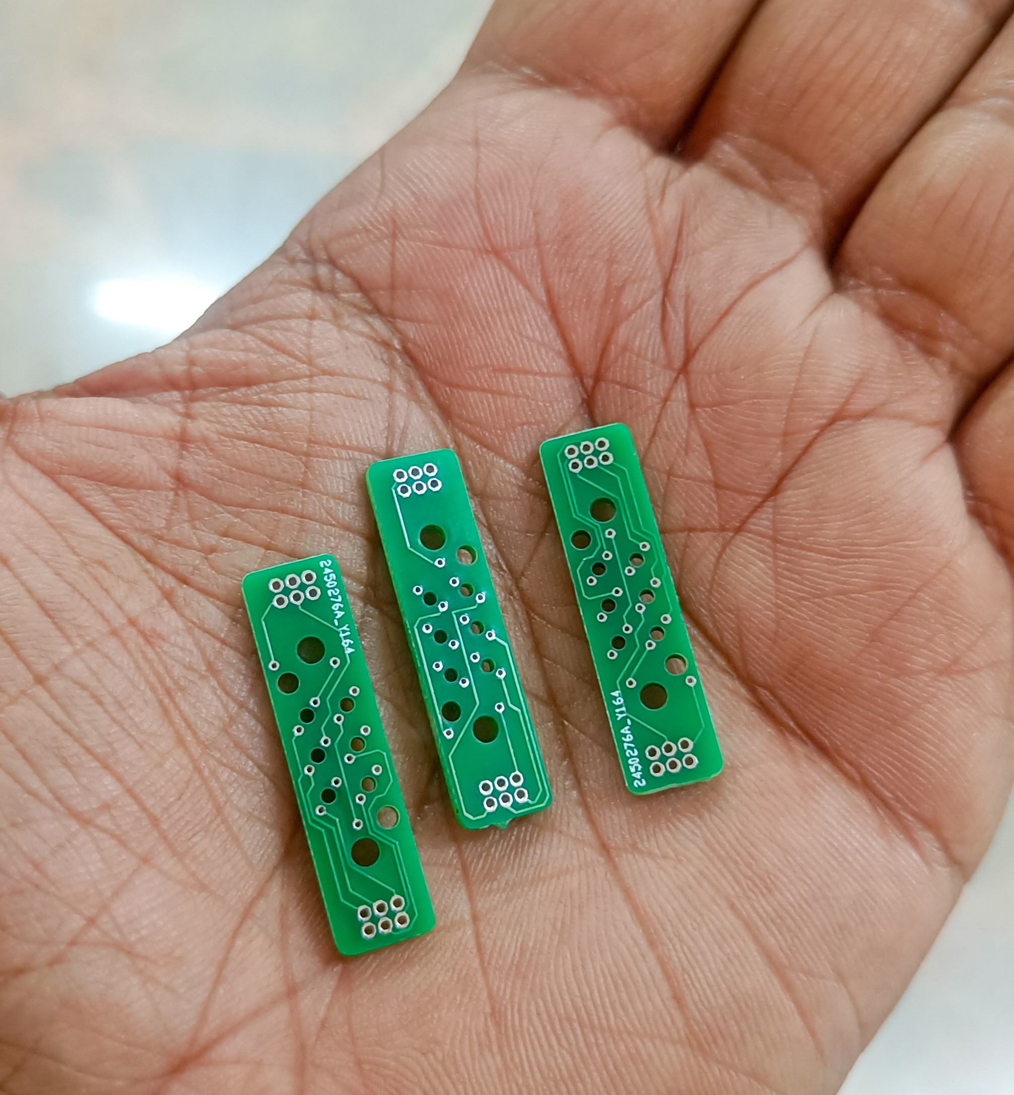
Construction:
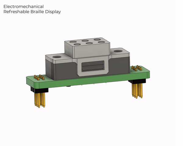
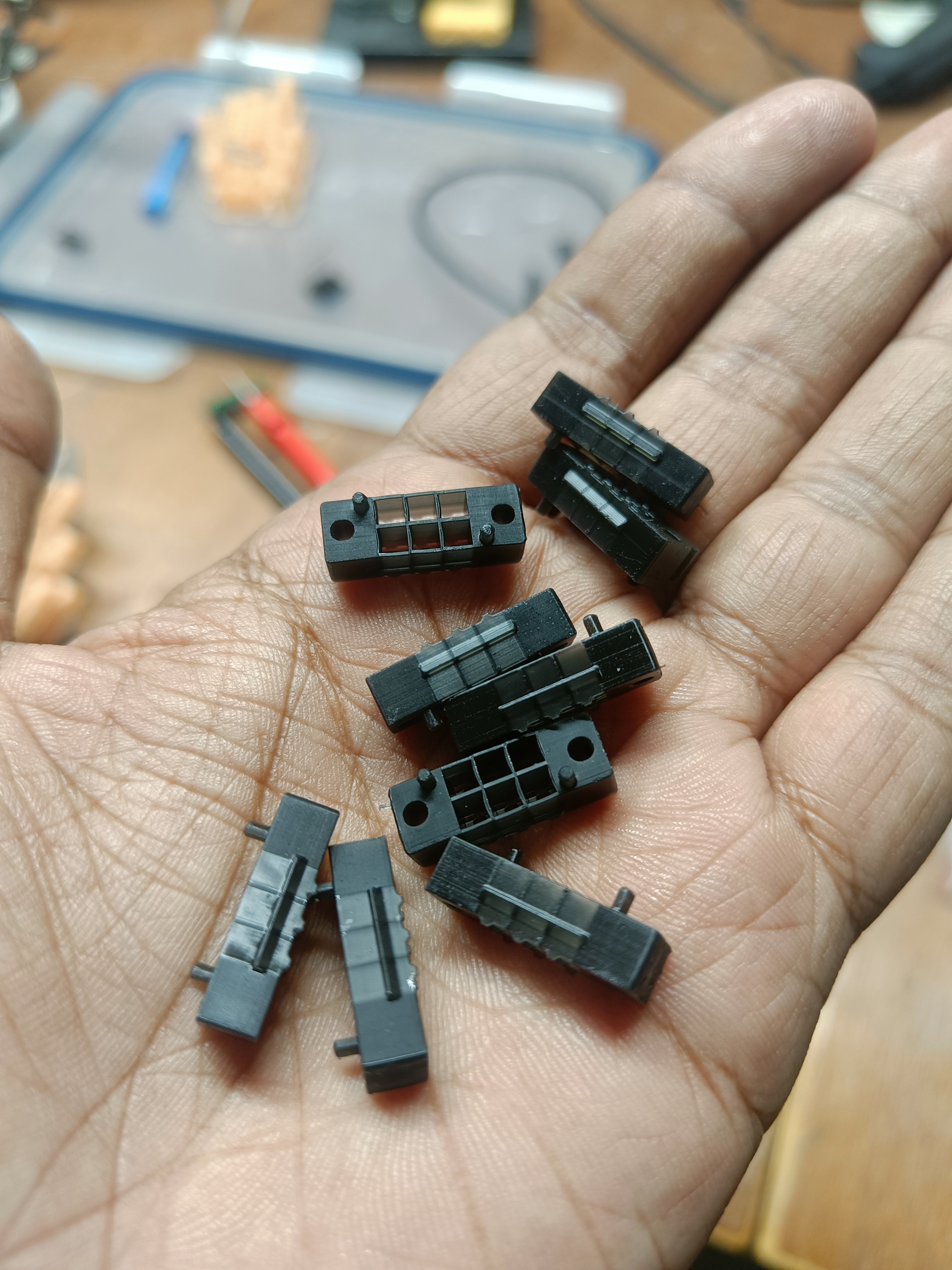
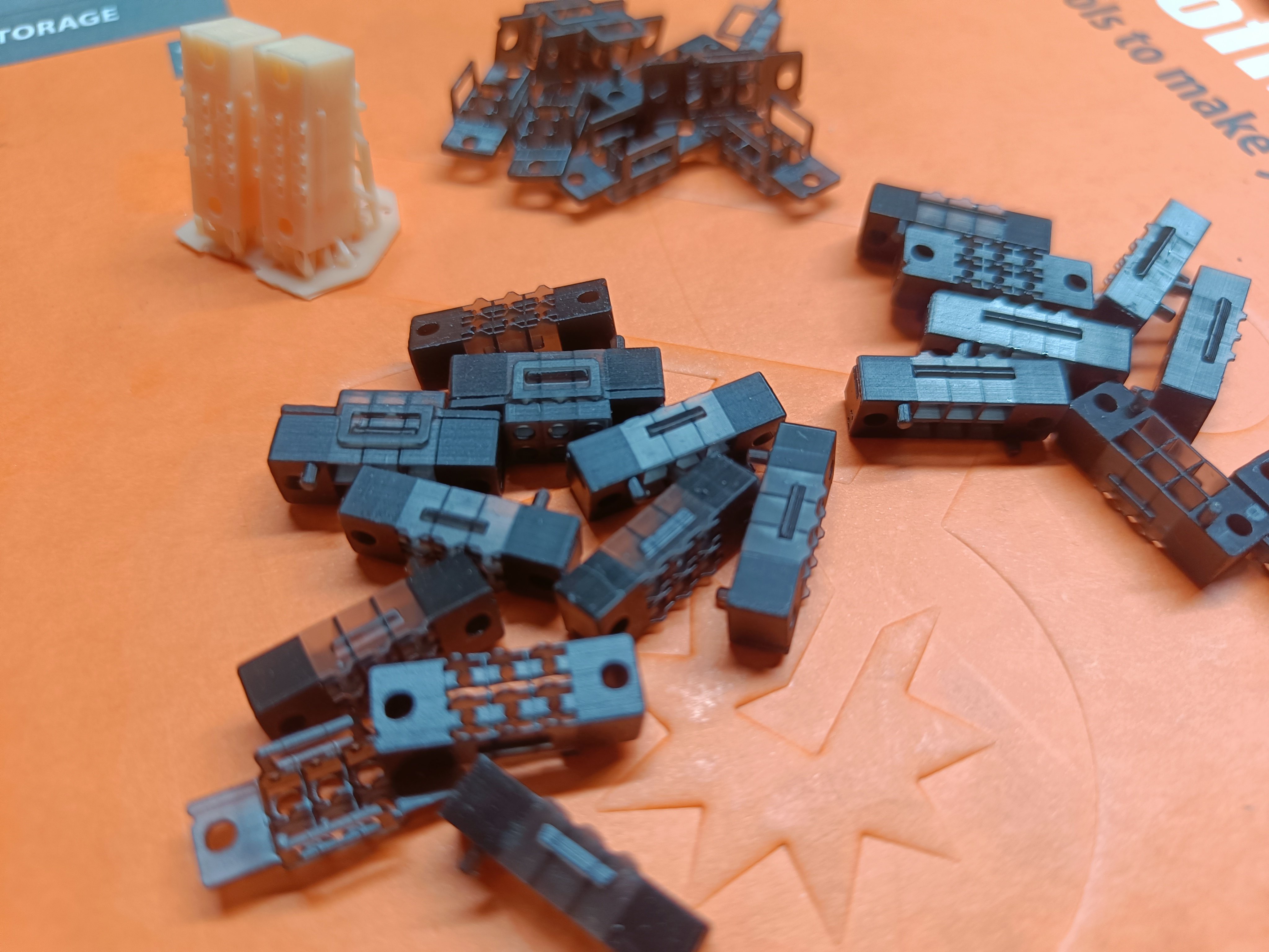
Fig. 4 Braille Cell Construction
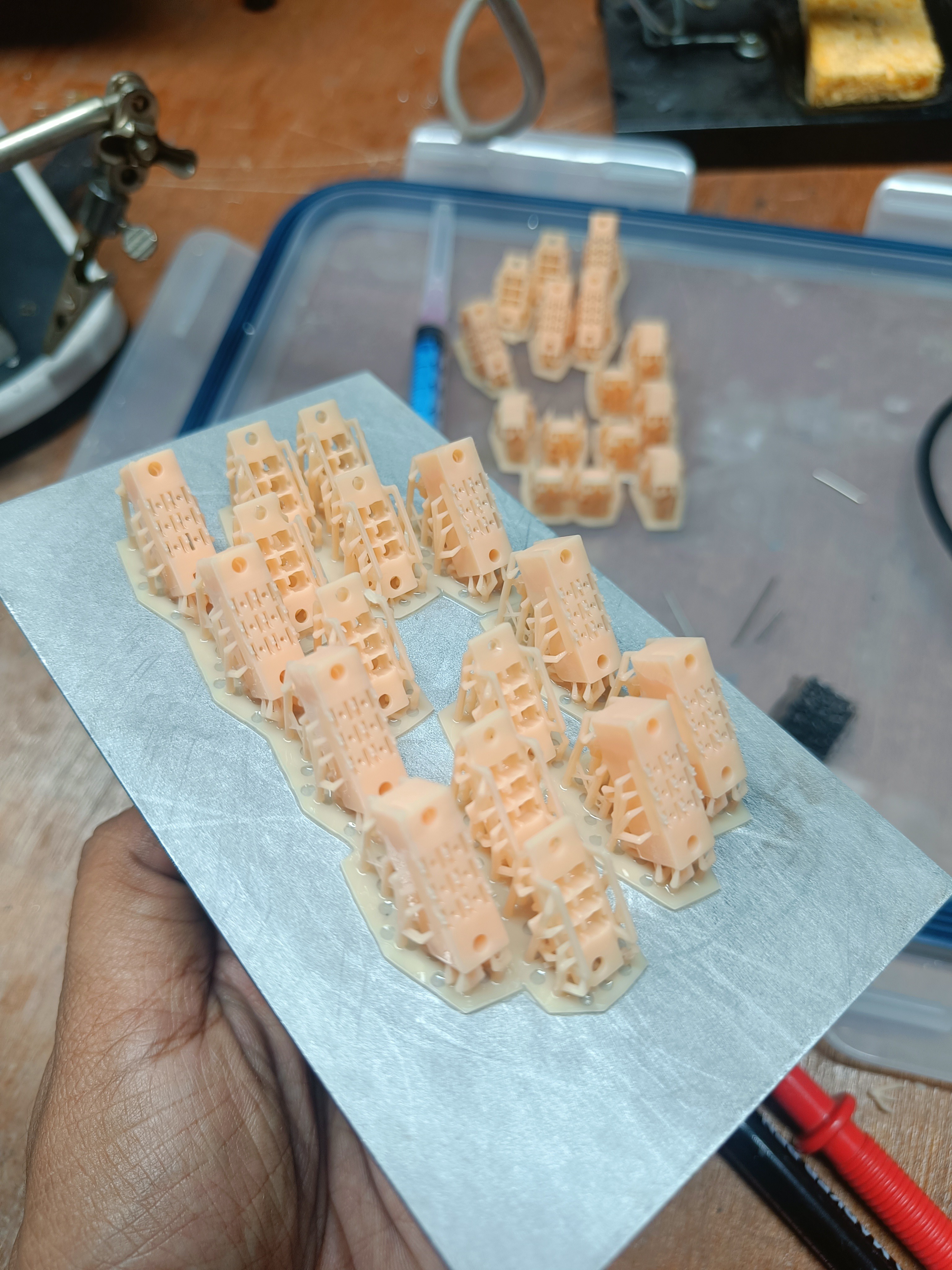
Prototyping is done using a high-resolution SLA 3D Printer as there are many thin-walled sections.
PR4 Resin on a 3D Systems Figure4 machine is being used for its ability to achieve 0.4mm wall thickness. Craftsman resin from Anycubic, on an Anycubic Photon Ultra, was tested to work as well.
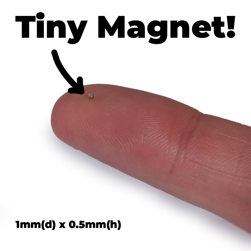
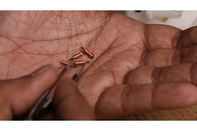
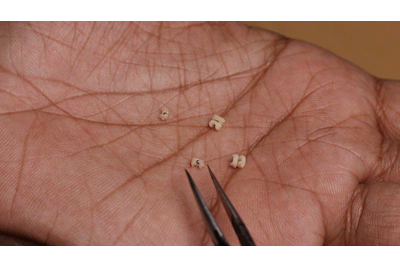
Fig. 5 Micromagnet
The micro 1mm x 0.5mm NdFeB magnet is what makes this project possible. Luckily there are now a handful of vendors around the world keeping these in stock as they are also used for things like jewelry clasps on thin bracelets, Kingdom Death miniatures, super thing Games Workshop miniatures, and more.
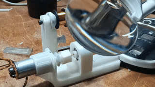
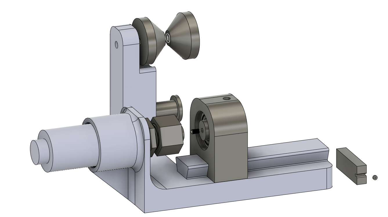
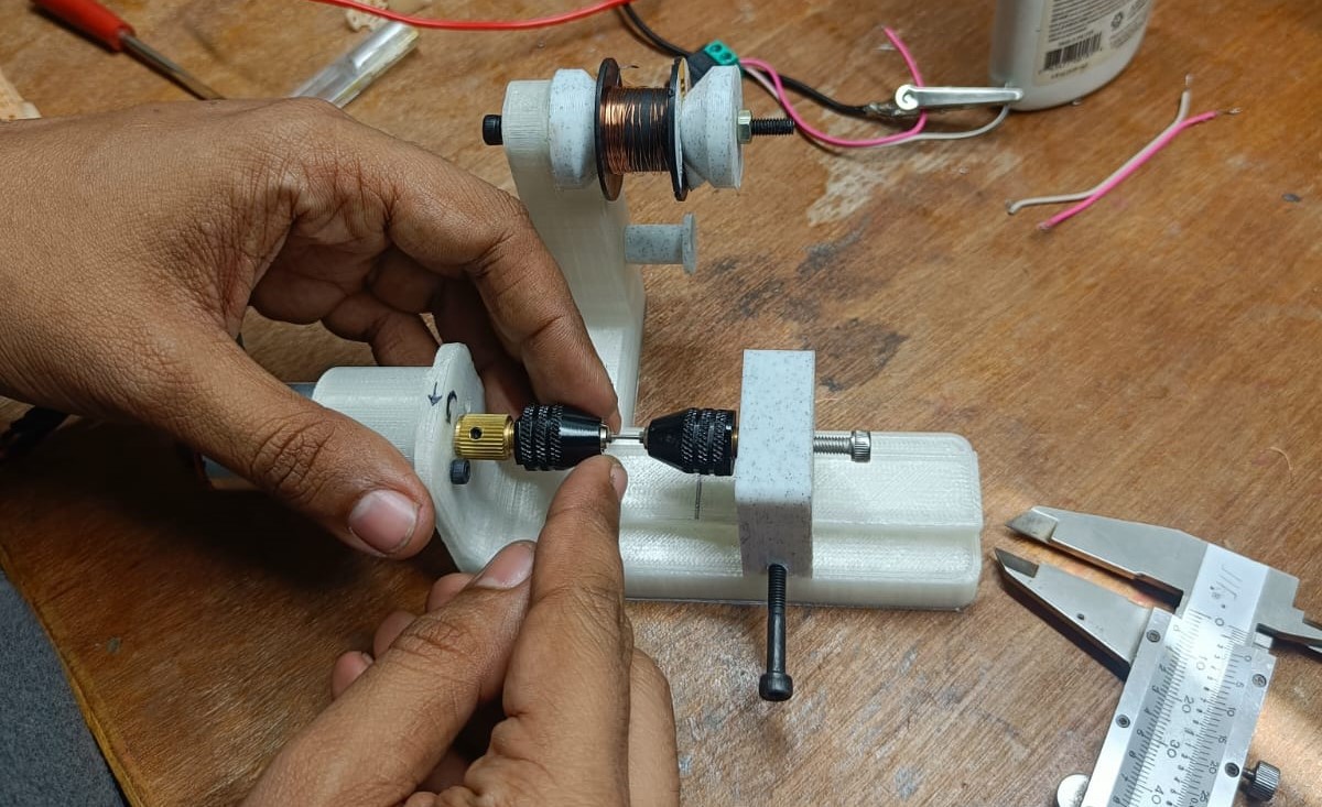
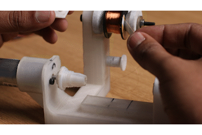
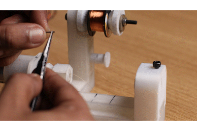
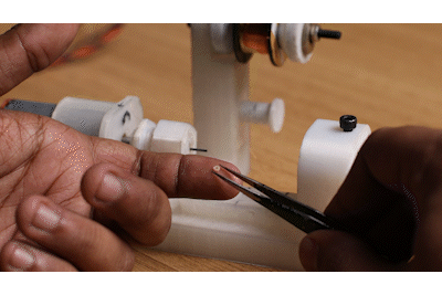
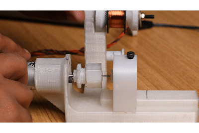
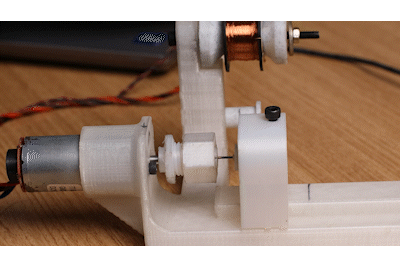
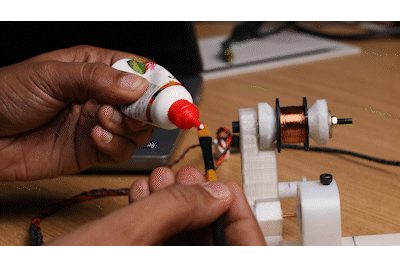
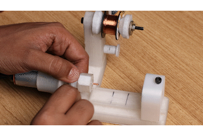
Fig. 6 Coil Winding Tool
The electromagnets are constructed with 50-micron enamel-insulated copper wire with a ferrite core. A 3D Printed winding tool makes winding such small electromagnets easy.
Apart from the winding tool, all standard assembly & soldering tools are sufficient to build your own braille modules.
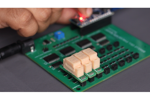
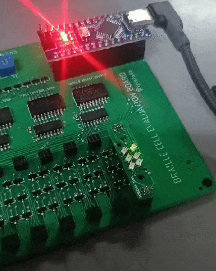
Fig. 7 Three Dot Array
Up to 3 Braille cells were tested to work together, no reason by more won't work as well. As only one pin is actuated at any time, only 1W of power is consumed at any point of time.
The only drawback of the drive system was that it takes at least 100ms to change the state of one pin, and this stacks up if more cells are added up. If we were to change the drive electronics so all pins of a single module can be driven simultaneously, then the refresh...
Read more »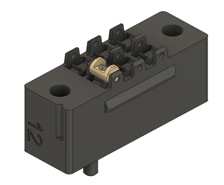


 Electroniclovers123
 electronicsworkshops
 Madaeon
 davedarko
Hey there! Great project. I am working on a robotics project which needs custom electromagnetic actuators just like the ones you made. I am trying to replicate the solenoid coils that you made. Can i please know what was the gauge of the wire, and the length of the coil ?