 OhmByOhm
Board Specifications
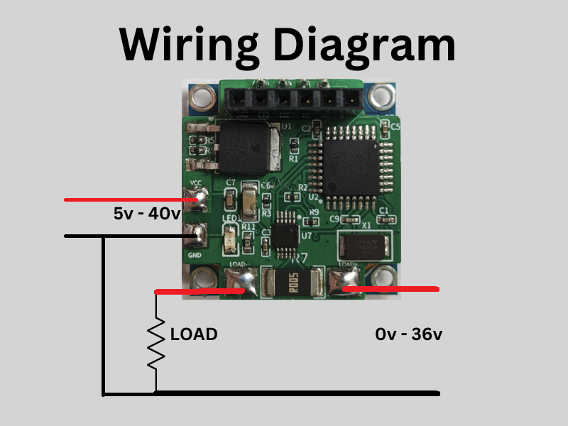
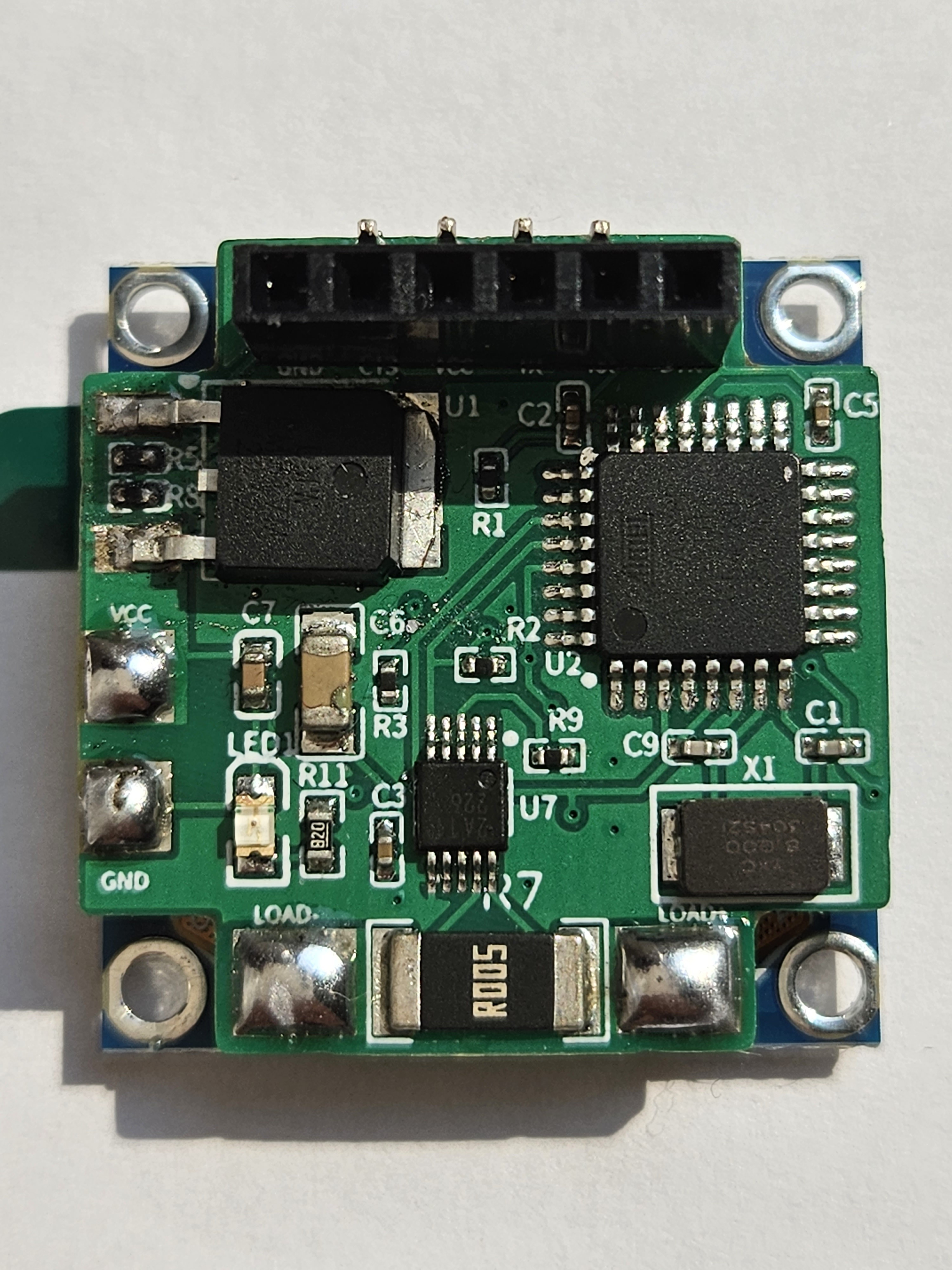
This Panel meter uses the SSD1306 OLED display and INA226 power monitor IC. The INA226 can measure voltages up to 36v and currents up to 5A with the 5mΩ high-side current sense resistor. The INA226 has an offset voltage max of 10 micro Volts and gain error of 0.1% to ensure high accuracy readings. There is an on board 3.3v LDO regulator with an input range of 5v-40v which powers everything on the board including display. This board contains an Atmega328p which is already programmed with the code in order to display Voltage from 0v-36v and currents from 0A-5A. In order to program the board differently and display power or change anything in the code, the user can use an FTDI programmer and simply plug it into the board's input pins.
Features
- 0-36V measuring range
- 0-5A (10A MAX) current measuring range
- Measure voltages as low as 5mV and currents as low as 5mA accurately
- Programmable Board
- 27mm x 28mm (1.06in x 1.1in) board size
- On board 3.3V regulator and ability to bypass regulator
- OLED Display


 Torbjörn Lindholm
 Gabor
Gabor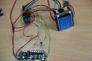
 jaromir.sukuba
 Ken Yap