 vishal soni
Below...
0%
0%
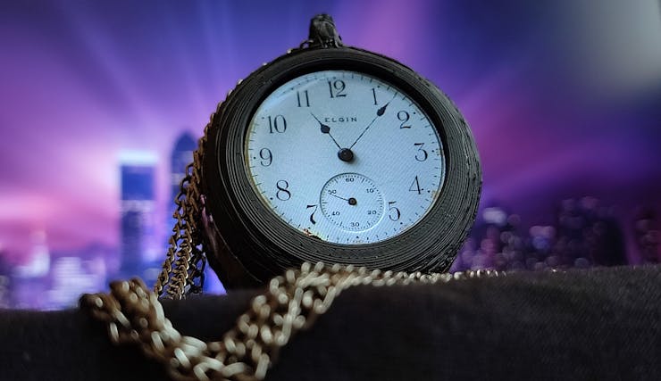
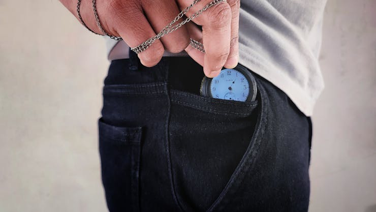
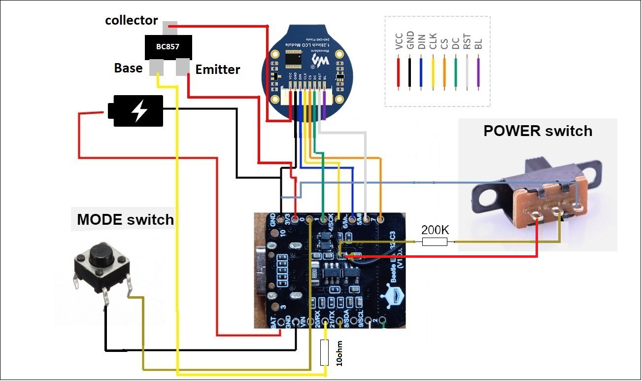
DigiPclock - a Digital Pocket Clock
I decided to create a watch that is both digital and has a vintage look. So I created digiPclock.
Become a Hackaday.io member
Already have an account? Log in.
Just one more thing
To make the experience fit your profile, pick a username and tell us what interests you.
Pick an awesome username
hackaday.io/
Your profile's URL: hackaday.io/username. Max 25 alphanumeric characters.
Pick a few interests
Projects that share your interests
People that share your interests


 EBP Controller
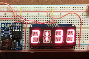
 Douglas Henke
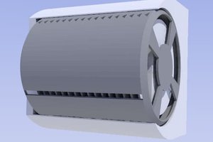
 Xasin
Xasin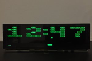
 Victor Serrano
If you set time via a web page, why enter hours and minutes manually? Most smartphones have their internal clocks already correctly set by navigation receiver, NTP or cellular network. Can the web page access this data and send it into the clock automatically?