 Hyr0n
Hyr0n `. ___
__,' __`. _..----....____
__...--.'``;. ,. ;``--..__ .' ,-._ _.-'
_..-''-------' `' `' `' O ``-''._ (,;') _,'
,'________________ \`-._`-','
`._ ```````````------...___ '-.._'-:
```--.._ ,. ````--...__\-.
`.--. `-` AND!XOR ____ | |`
`. `. ,'`````. ; ;`
`._`. __________ `. \'__/`
`-:._____/______/___/____`. \ `
| `._ `. \
`._________`-. `. `.___
`------'`We wanted to build upon what we did at DC24 with an even more hackable badge. But we’re taking a different route from last year. No POS Arduino IDE, no specialized STM32 framework, no USB, or special drivers. This year the badge is scriptable. We didn’t want hackers spending their con configuring an arcane build environment. We want you to hack the badge on day 1, share you hacks during the con, and show us all the great things you can do. So what have we done? We’ve embedded a scripting engine. Not only that but we’ve created basic, easy-to-understand APIs for almost everything in the badge. As much as we could come up with. We looked at Python but was not impressed with anything out there. We even had a Javascript engine running on the badge at one point, but it used 25% of the flash space, we needed that for bling. We ended up adopting a very limited TCL engine. Your favorite TCL scripts won’t run on the badge, that’s not the point.
Badge TCL Language Support
- Badge supports command grouping with double quotes “ ”, braces { }, and brackets [ ].
- Badge also supports variable substitution with $.
- Badge does not support regular expressions.
- Note that some commands are executed in RPN (Reverse Polish Notation)
The following commands are supported:
- set
- subst
- puts
- proc
- if
- for
- while
- return
- break
- continue
- Mathematical expressions
- + , - , * , / , > , >= , < , <= , == , !=
Special Commands
- cls
- Clears the screen
- delay <ms>
- Pauses execution for specified milliseconds
- incr <variable>
- Increments the given variable by 1
- io_read <pin>
- Returns 1 for high or 0 for low
- io_write <pin> <HIGH|LOW>
- Sets the given pin to high or low
- led_set <index> <red> <green> <blue>
- Sets RGB value of the given led
- led_set_hsv <index> <hue> <saturation> <value>
- Sets HSV value of the given led. Where hue, saturation, and value are 0-100.
- play <path/to/raw/file>
- Plays the given raw file once.
- print <x> <y> <message>
- Prints the message coordinates x,y
- rand <max>
- Returns a value between 0 and max.
- set_color <color>
- Sets current color for printing text
- circle <x> <y> <radius> <color>
- Draws a circle with radius at x,y and given color
- image <x> <y> <width> <height> <path/to/raw/file>
- Draws raw file at x,y with given width and height
- line <x1> <y1> <x2> <y2> <color>
- Draws a line x1,y1 to x2,y2 and given color.
- rect <x> <y> <width> <height> <color>
- Draws an empty rectangle with given width and height at x,y
- fill_rect <x> <y> <width> <height> <color>
- Draws a filled rectangle with given width and height at x
- pixel <x> <y> <color>
- Draws a single pixel at x,y and given color.
- scroll <message>
- Scroll the message once
- triangle <x1> <y1> <x2> <y2> <x3> <y3> <color>
- Draws empty triangle at x1, y1, to x2, y2, to x3, y3 with given color
- up
- Returns 1 if up button is currently pressed
- down
- Returns 1 if down button is currently pressed
- left
- Returns 1 if left button is currently pressed
- right
- Returns 1 if right button is currently pressed
- action
- Returns 1 if action button is currently pressed
- button_clear
- Clears current button state, useful for preventing button holding
- button_state
- Returns state of all buttons as a 8-bit mask
- button_wait
- Blocks execution until any button is pressed
Color support
Graphics and fonts support 8 bit color. Format is RRRGGGBB. See:
https://en.wikipedia.org/wiki/8-bit_color
Some examples:
0: Black
3: Blue
28: Green
252: Yellow
224: Red
GPIO
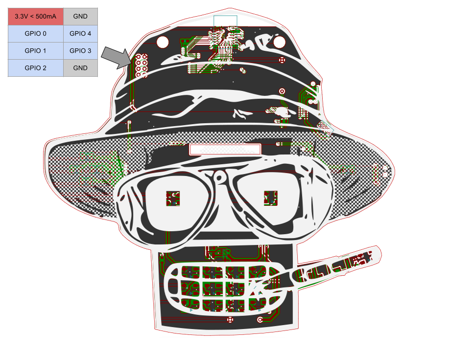 Basic GPIO io_read and io_write commands have been implemented. The PCB has a total of five IO exposed. This was all that was left after all the bling was done. Each IO is referred to as 0 through 4 in the TCL code. Note 3.3v power is also provided for addons if you desire.
Examples
There are examples included on the badge, here is their source code.
They are located in: /SD Image/TCL/
Drop any TCLish scripts you create in this directory.
EXAMPLE1.TCL: Prints blue and green text to the screen just like your first BASIC program.
cls;

print 10 10 "Hello World!";
delay 500;

set_color 3;
print 30 30 "Blue";
delay 1000;

set_color 28;
print 30 60 "Green";
delay 5000;
EXAMPLE2.TCL: Scrolls a message on the screen.
scroll "Hello World! This is MAN BEAR PIG TCL!";EXAMPLE3.TCL: Plays Rick Roll until user holds a button
cls;
print 0 0 "Hold any button to quit rick roll";
delay 2000;

while {== [button_state] 0} {
	play "/BLING/AND!XOR/RICKROLL.RAW";
};
EXAMPLE4.TCL: Cycles the eye color hues.
cls;
print 0, 60 "The Eyes!";

for {set h 0} {< $h 100} {incr h} {
	led_set_hsv 12 $h 100 100;
	led_set_hsv 13 $h 100 100;
	delay 100;
};
EXAMPLE5.TCL: Prints text in the middle of the screen using ascii conversions
cls;

set base 42;
set w 4;
set x 0;
set y 60;
print [* $w $x] $y [chr [+ $base 79]];
incr x;
print [* $w $x] $y [chr [+ $base 53]];
incr x;
print [* $w $x] $y [chr [+ $base 23]];
incr x;
print [* $w $x] $y [chr [+ $base 36]];
incr x;
print [* $w $x] $y [chr [- 100 $base]];
incr x;
print [* $w $x] $y [chr [+ 66 $base]];
incr x;
print [* $w $x] $y [chr [+ 72 $base]];
incr x;
print [* $w $x] $y [chr [+ 36 $base]];
incr x;

delay 5000;
EXAMPLE6.TCL: Demonstrates drawing graphics to the display
cls;

for {set c 0} {< $c 256} {incr c} {
	fill_rect 0 0 128 128 $c;
	print 0 0 $c;
	delay 100;
}

image 0 0 128 128 "TCL/BENDER4.RAW";

line 128 0 0 128 252;
line 0 0 128 128 224;
line 0 62 128 62 3;

circle 96 32 8 224;

triangle 12 12 48 48 0 50 255;

rect 80 80 40 20 150;

fill_rect 10 80 10 40 100;

delay 5000;
EXAMPLE7.TCL: Toggles IO 0 on and off
cls;
print 0 0 "Toggling IO 0 Low/High 100 times"

for {set i 0} {< $i 100} {incr i} {
	fill_rect 0 64 128 20 0
	print 0 64 $i
	io_write 0 HIGH;
	delay 400;
	io_write 0 LOW;
	delay 400;
}
EXAMPLE8.TCL: Prints random numbers to the screen
print 0, 0 "Random numbers"
print 0, 10 "< 100"
print 64, 10 [rand 100];
print 0, 20 "< 20"
print 64, 20 [rand 20];
print 0, 30 "< 100000"
print 64, 30 [rand 100000];
print 0, 64 "Press any button to continue"
button_wait;
Discussions
Become a Hackaday.io Member
Create an account to leave a comment. Already have an account? Log In.
anyway you could make it easy to do i2c on the GPIO pins? I'd like to hook up an RTC.
Are you sure? yes | no