 Kevin Santo Cappuccio
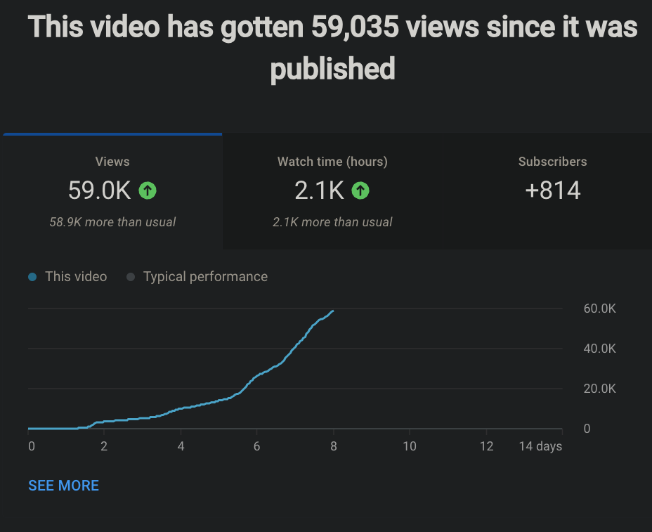
Hackaday Prize 2023 Entry Video
If you don't want to read through my walls of text, this video should give a good general overview of what this thing can do.
If you have one or want to hang out with people who do, check out the Jumperless Forum or the Jumperless Discord
Deets
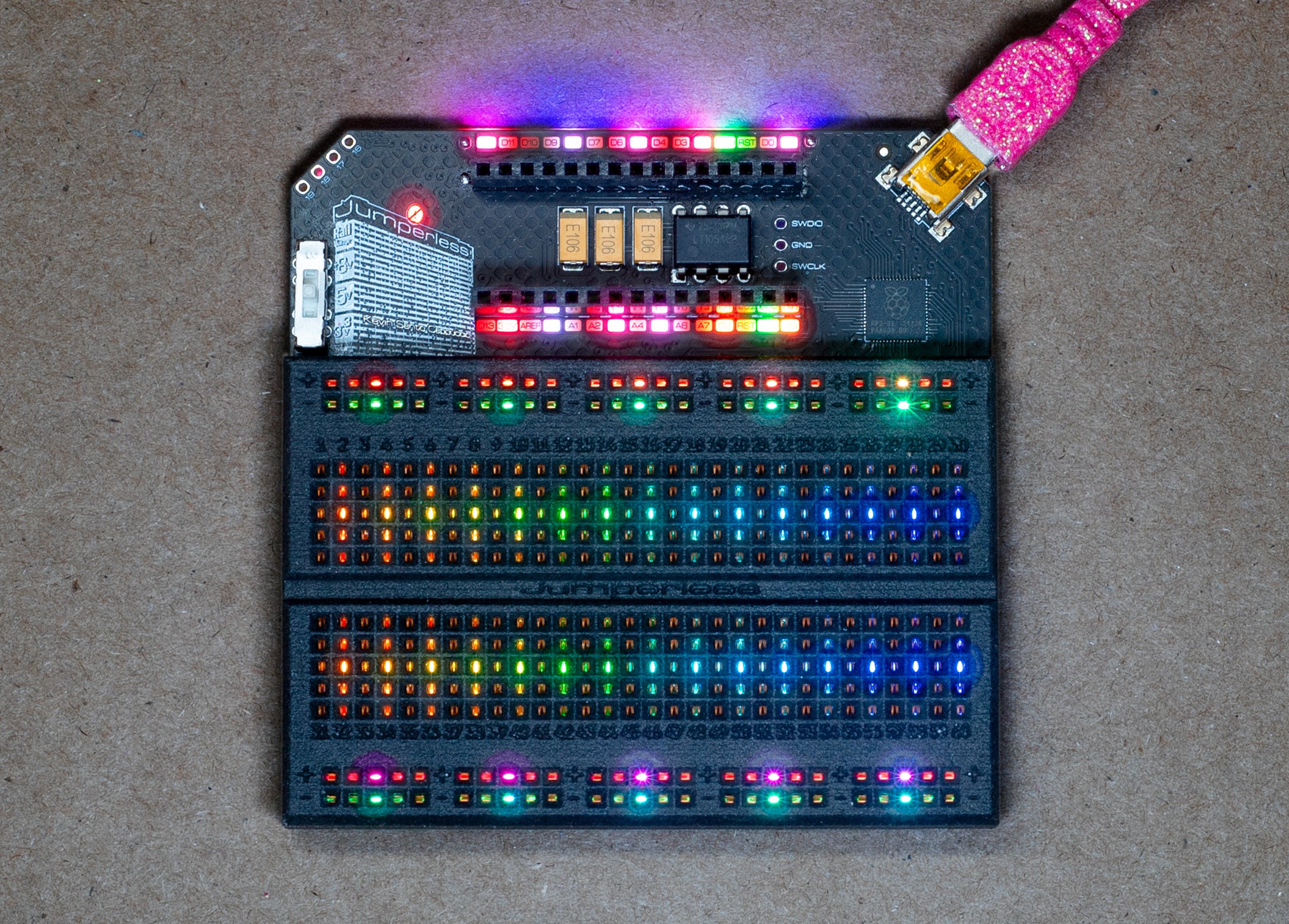
The connections are real and fully analog (-8V to +8V, up to around 1 MHz before signal quality starts to degrade) instead of cheating with some measure-then-simulate setup, although you can do that too if you want to simulate a memristor or to send jumpers over the internet.
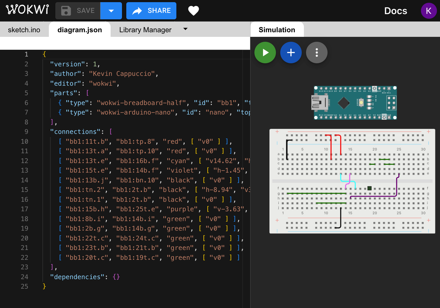
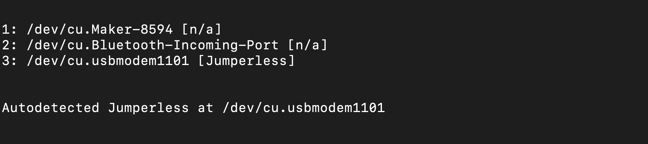
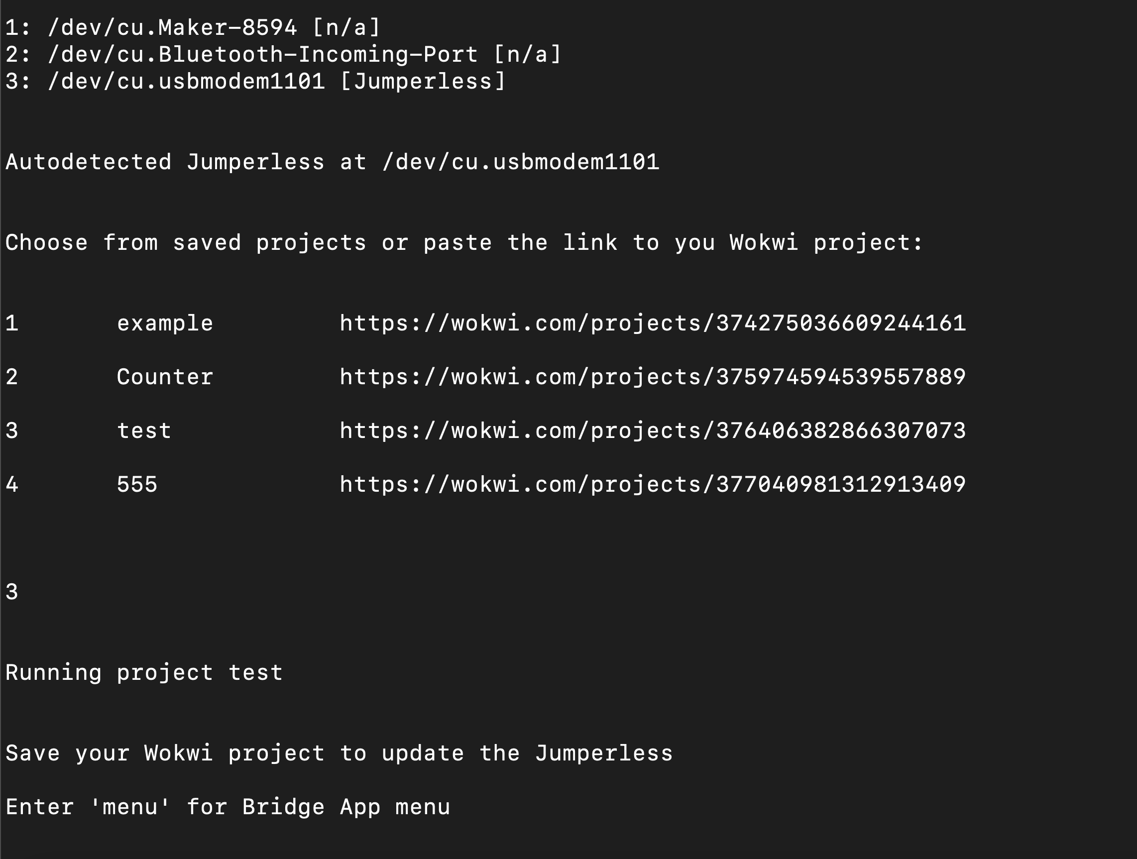
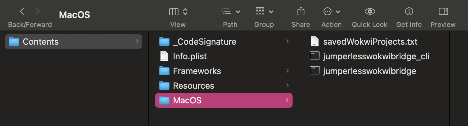
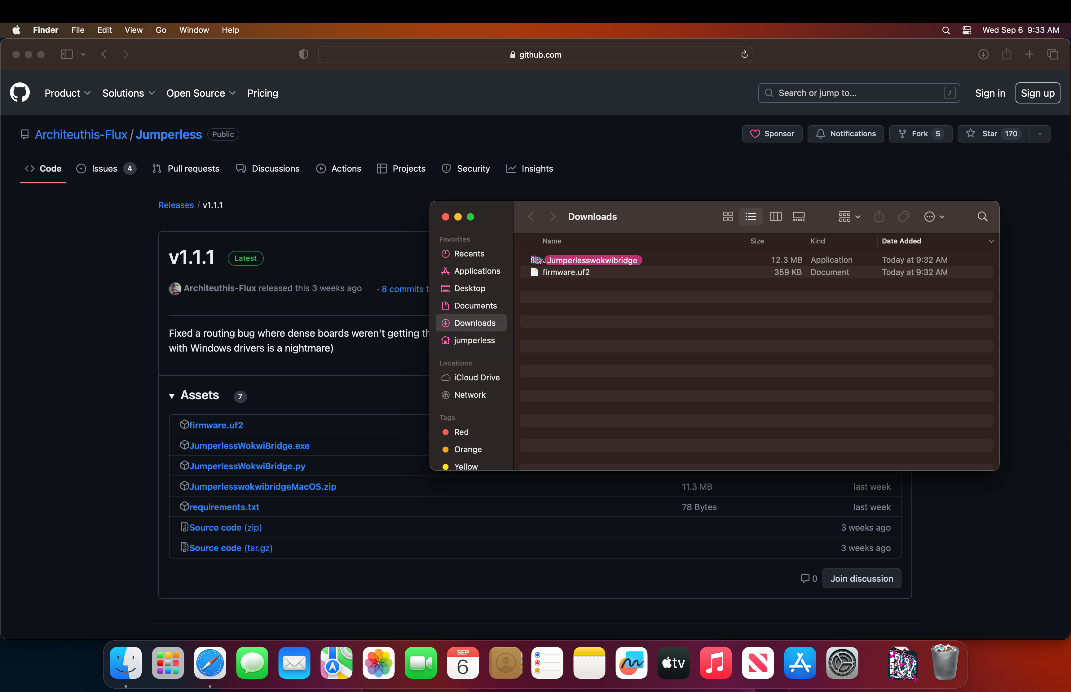
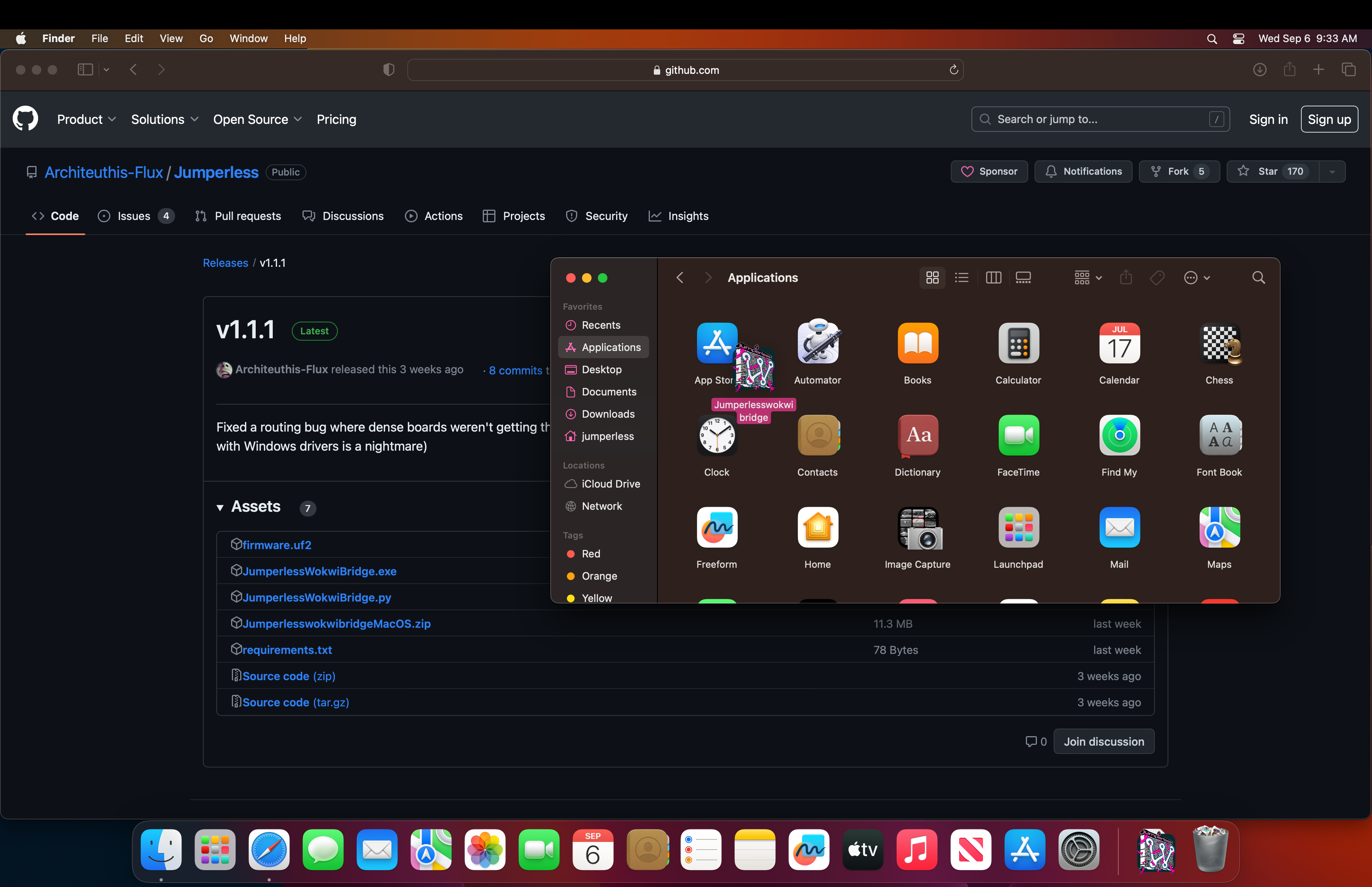
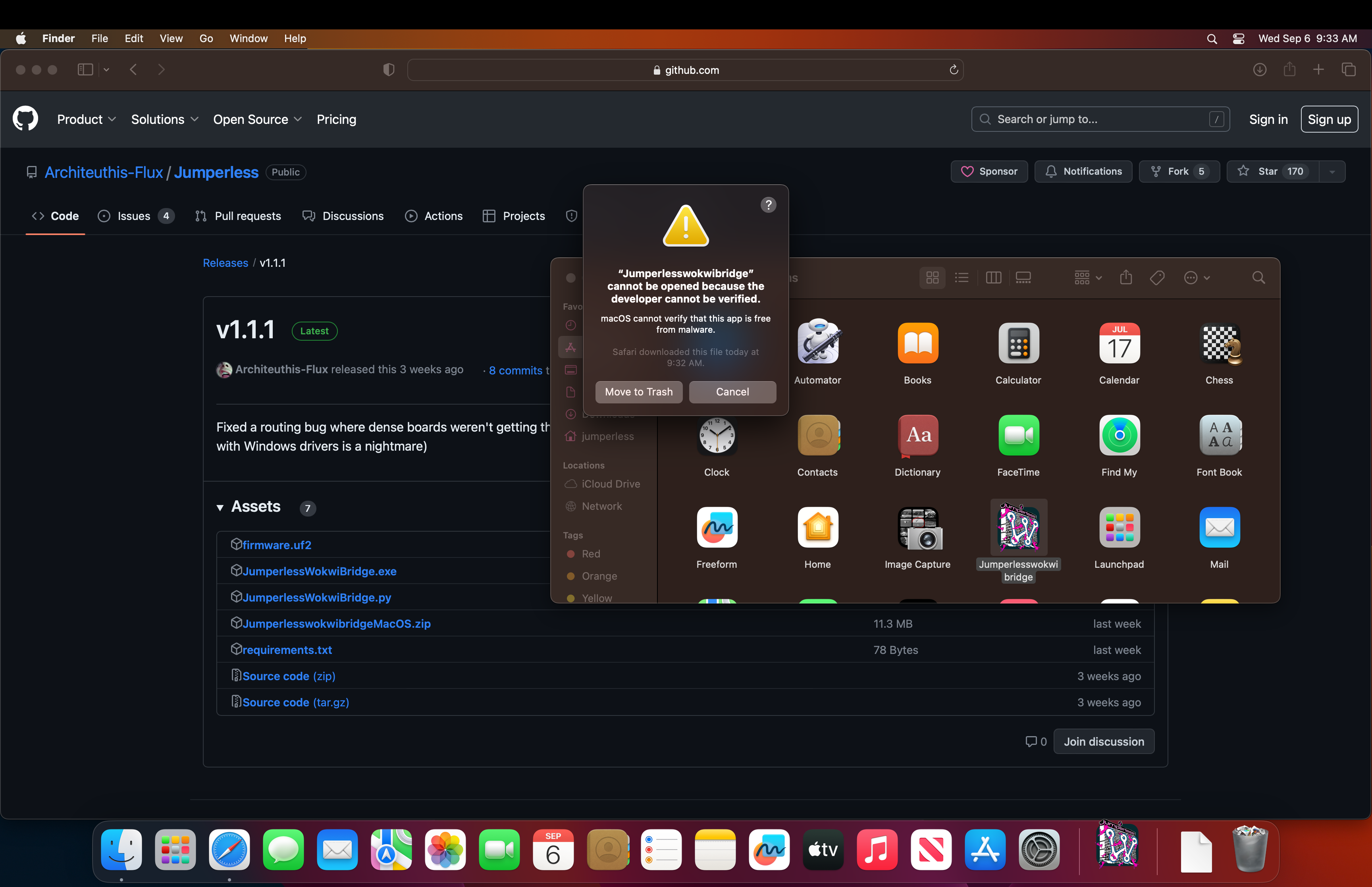
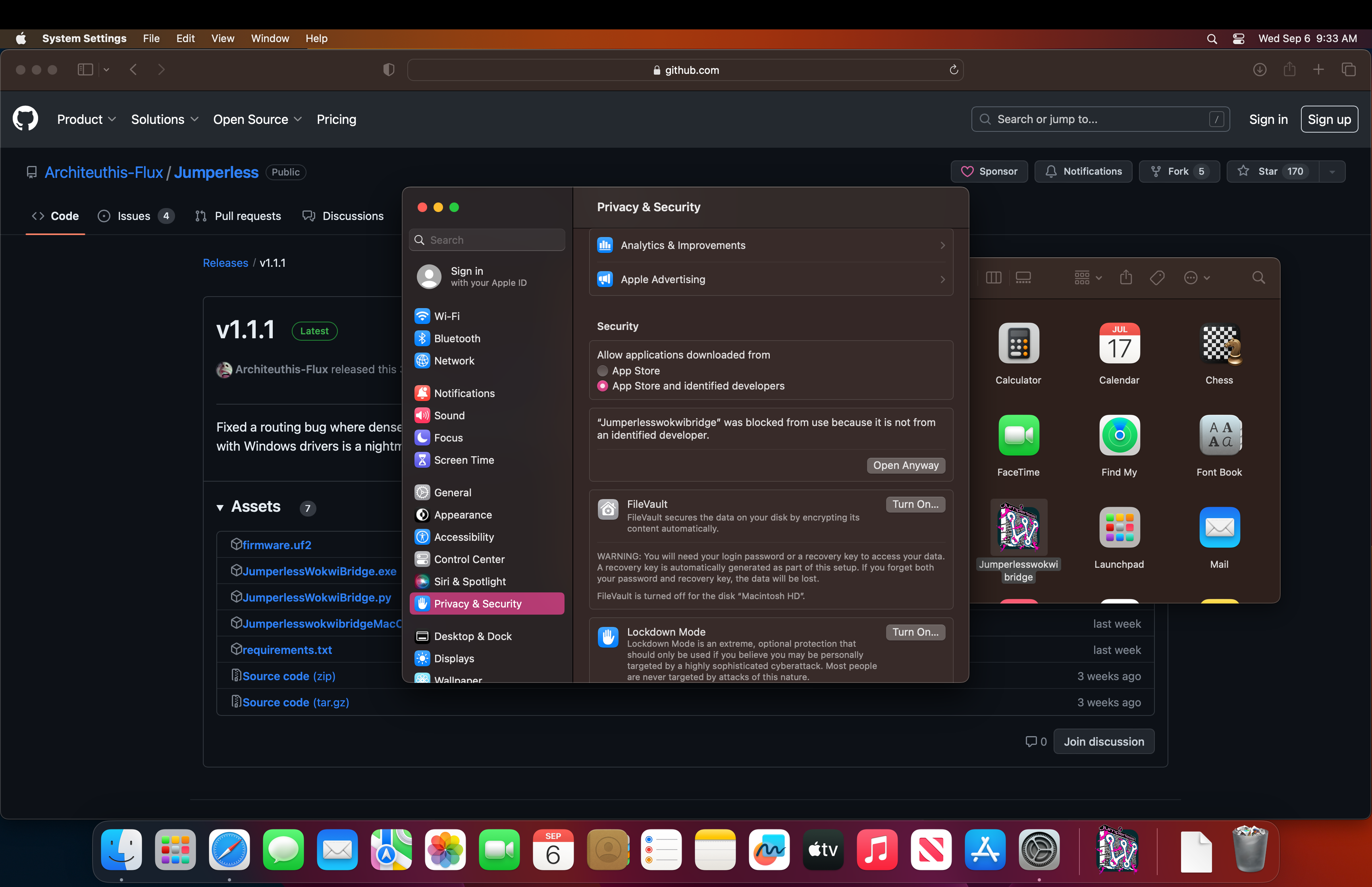
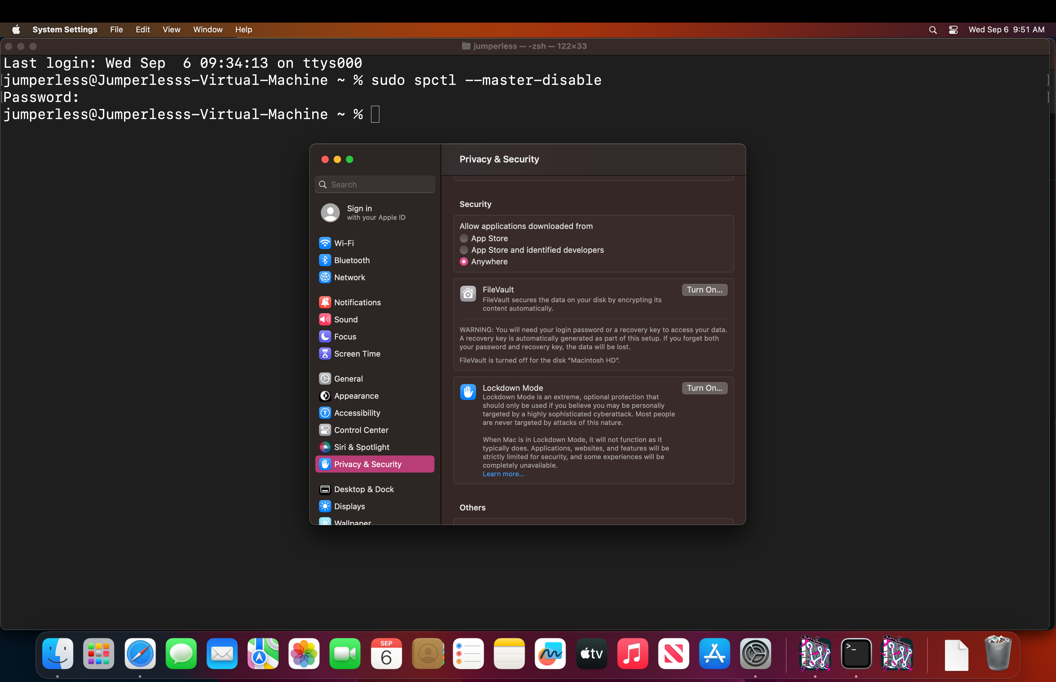
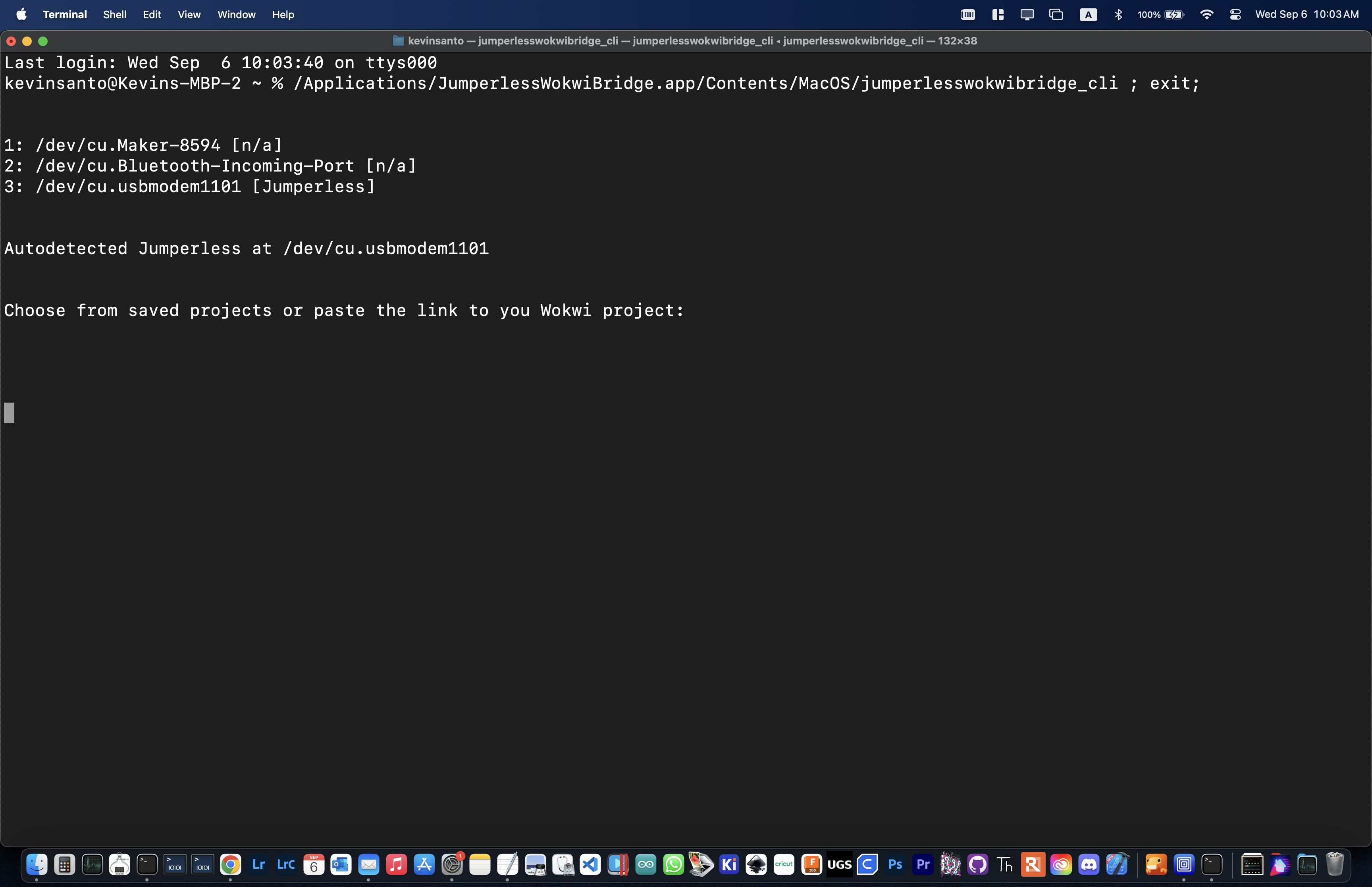
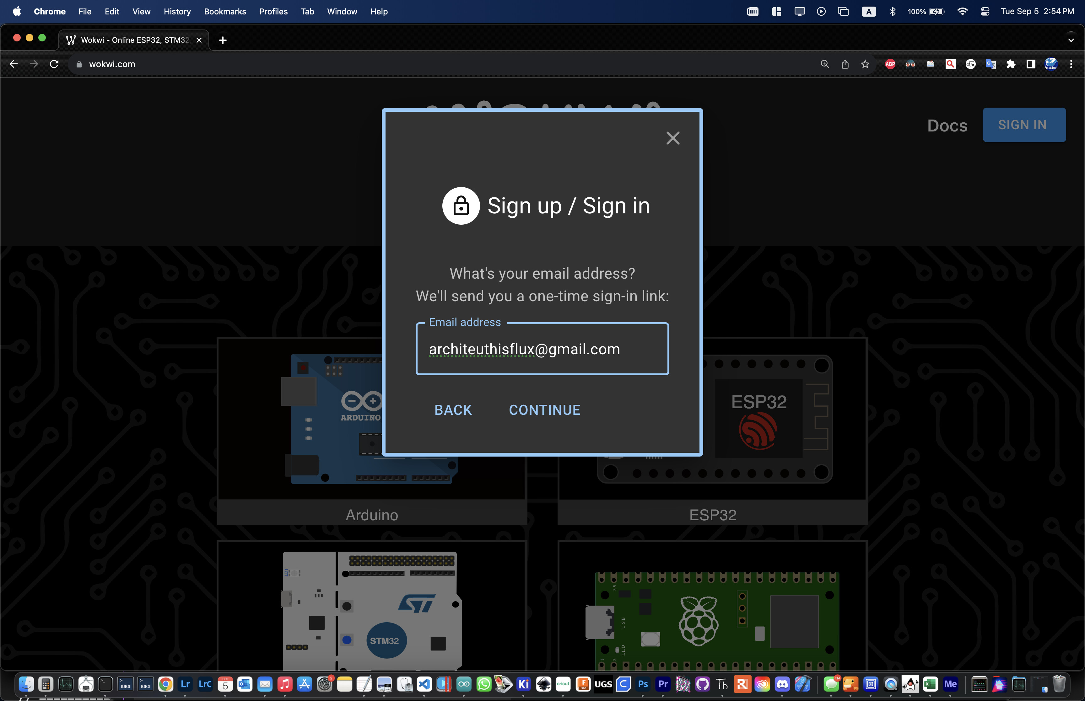
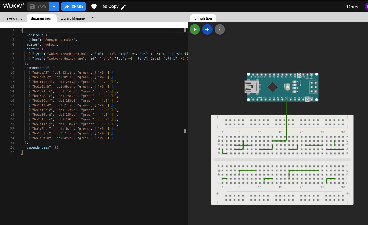
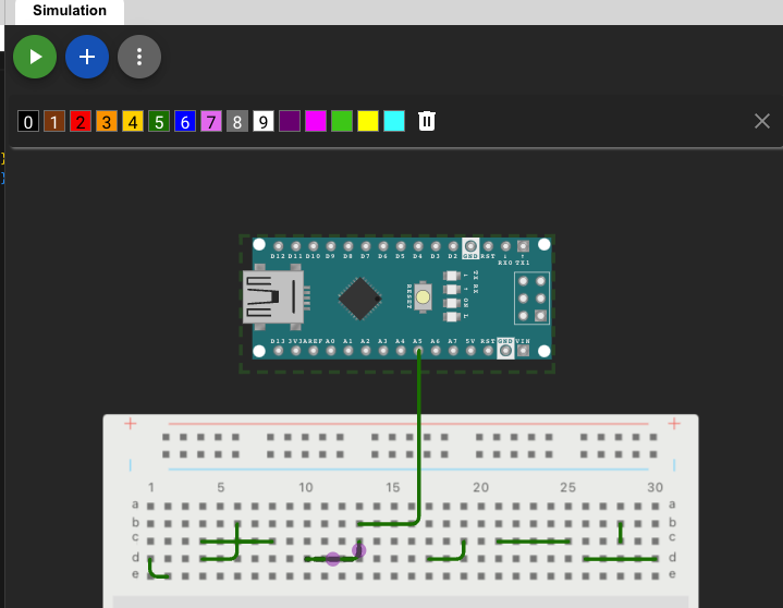
Currently, the best way to make connections is using Wokwi while running the Jumperless Wokwi Bridge app on your computer. It's a Python script and command line interface that automatically pulls any changes you make to your Wokwi project and sends them to the Jumperless.
Here's a video of me connecting an OLED display to an Arduino
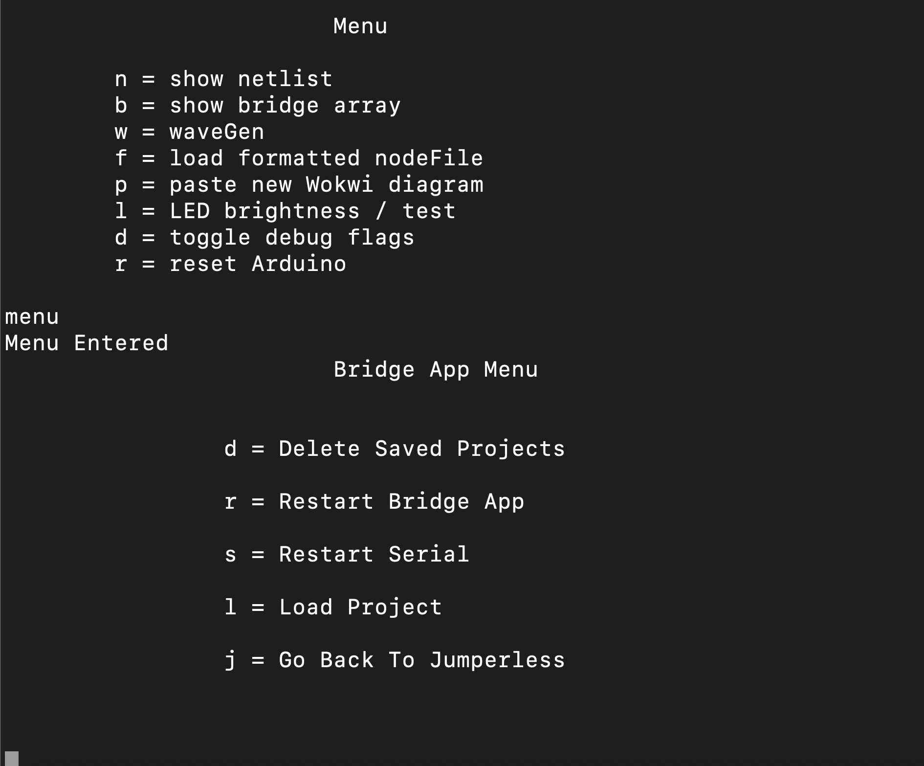
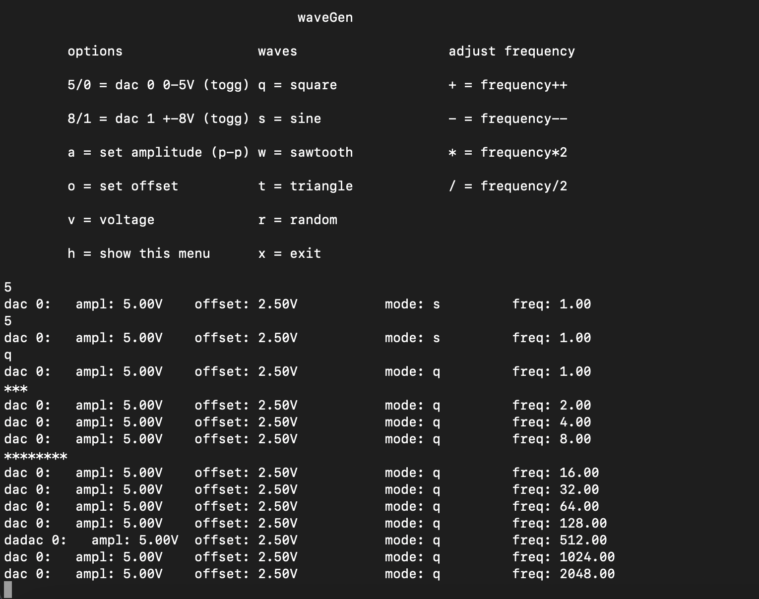
It also passes through all the serial communications to and from the Jumperless so you can use the text-based menus to do things like running the wave generators, measuring current/voltage, and looking debug output on the Jumperless directly at the same time.
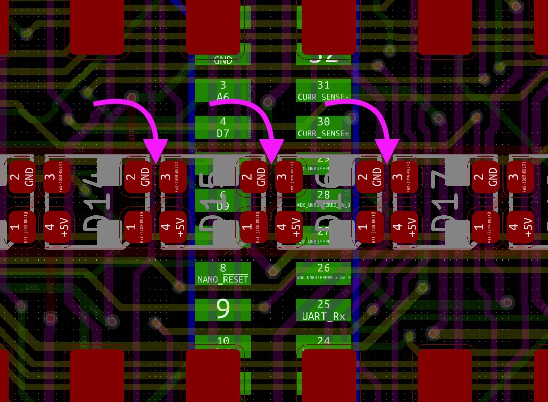
The latest firmware update now has the Jumperless show up as 2 USB devices, so you can connect the second one to the Arduino Nano and flash the firmware and communicate via Serial through one USB cable as if they were both plugged in separately. You can also route the UART Tx and Rx lines anywhere and talk to things just like you would with one of those cheap USB-Serial boards. More details about that here.

Pretty soon there will be an Arduino Library where you can make connections and measure stuff with an API that will look something like jumperless.connect(row1, row2); or jumperless.measureVoltage(row); that can either be run on the Arduino Nano (sending commands via UART to the RP2040) or the Jumperless itself.
Hopefully this will allow people to write cool stuff for the Jumperless to do that I haven't even thought of and wouldn't be possible on a regular breadboard.
Also there will be a Python Module that does the same stuff as above, which can either be run in an onboard MicroPython interpreter or on a computer.
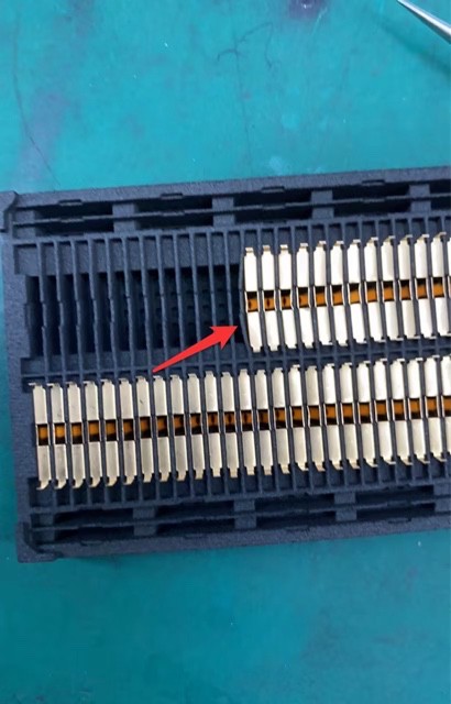
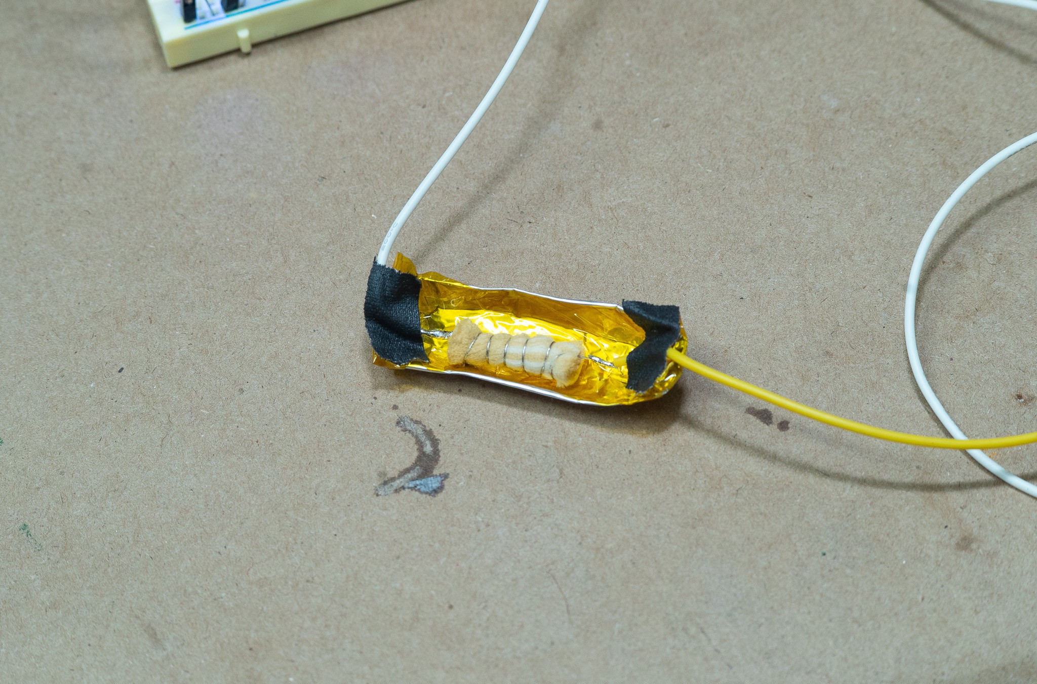
Here's another video of me using the Jumperless to figure out the pinout of an LED matrix. I'm actually not faking it in this video, I couldn't find a datasheet.
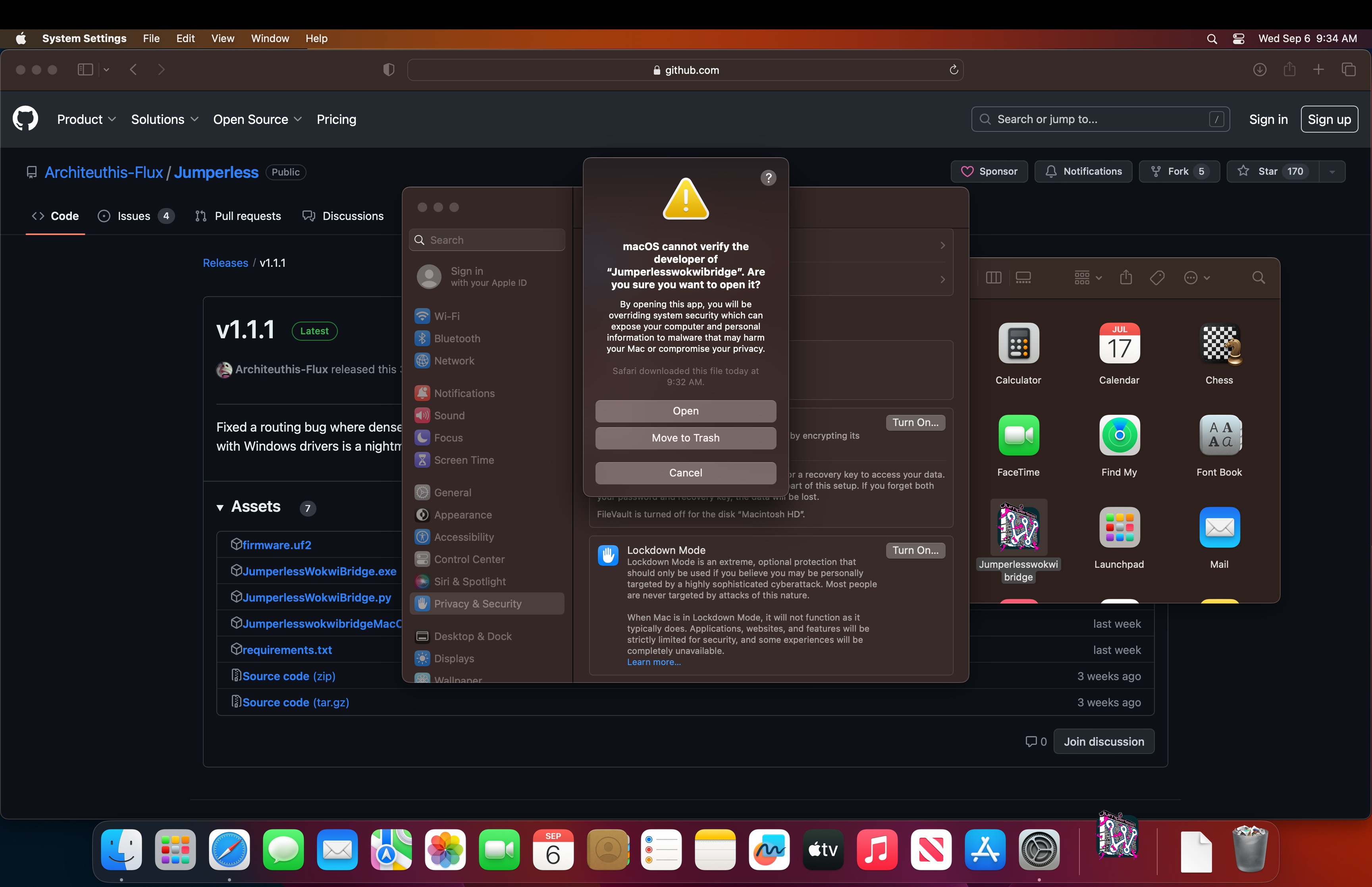
Firmware and stuff
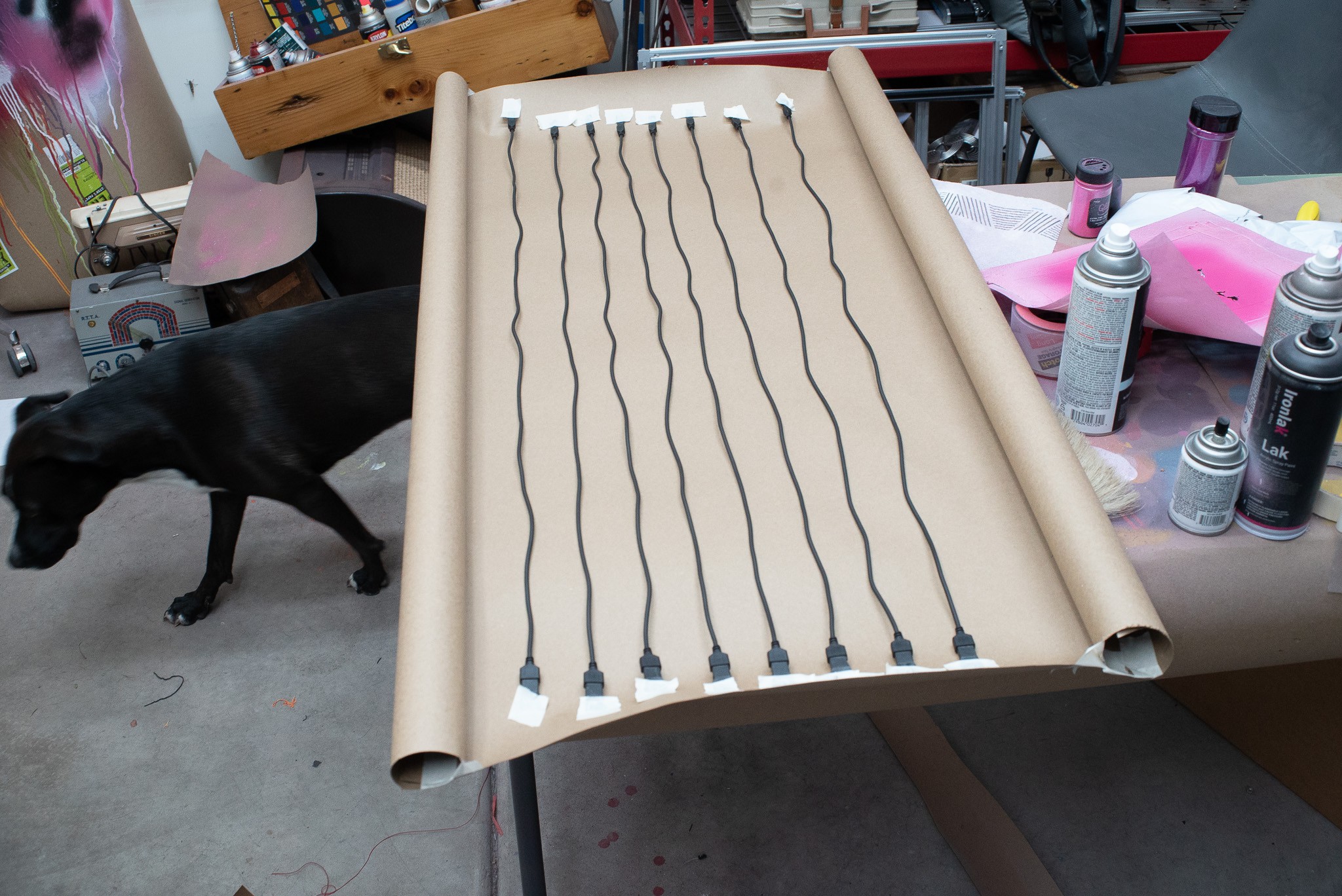
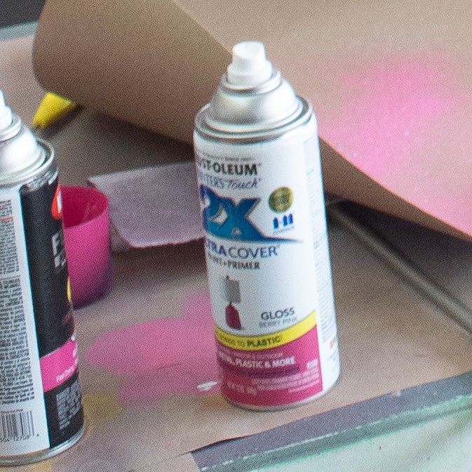
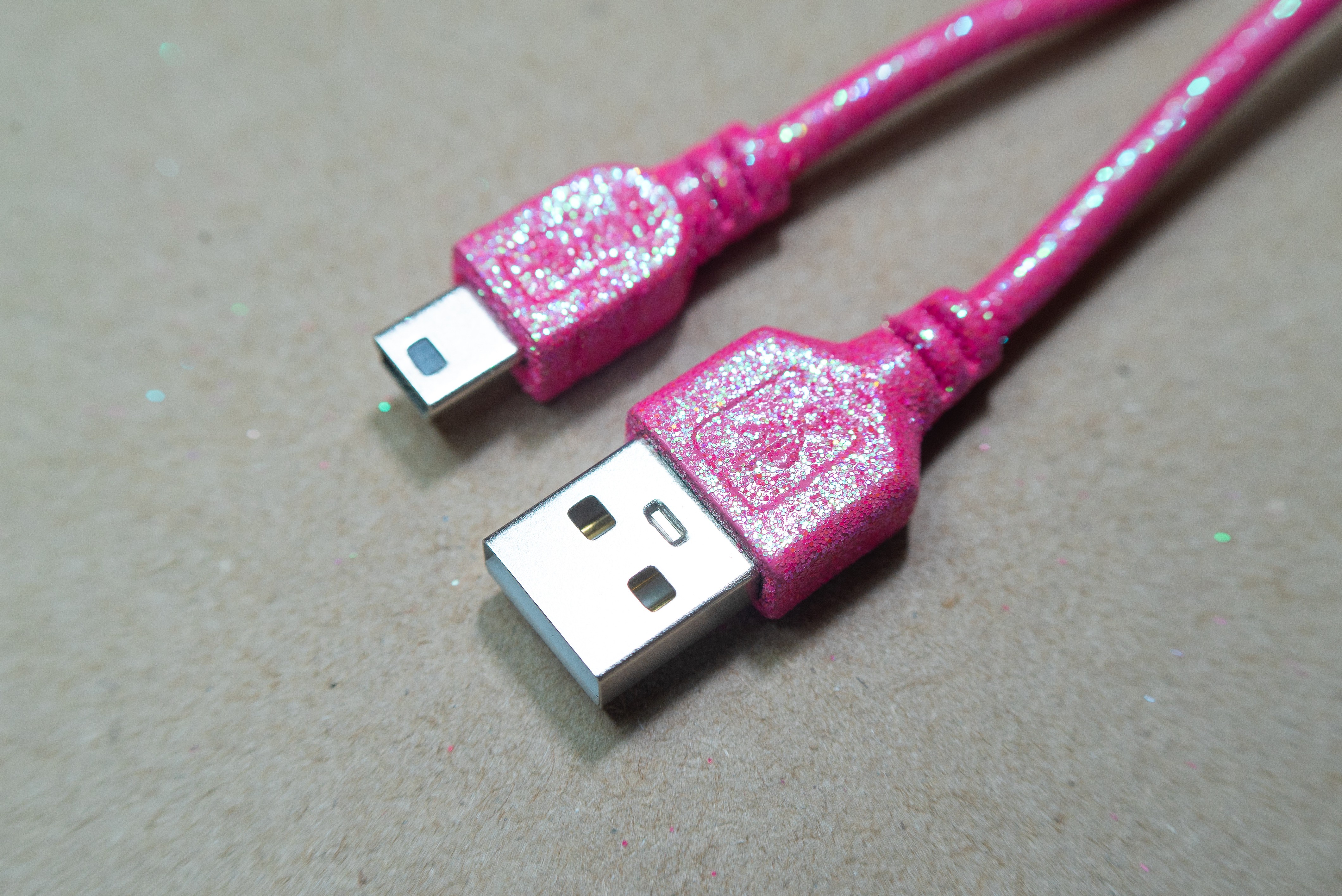
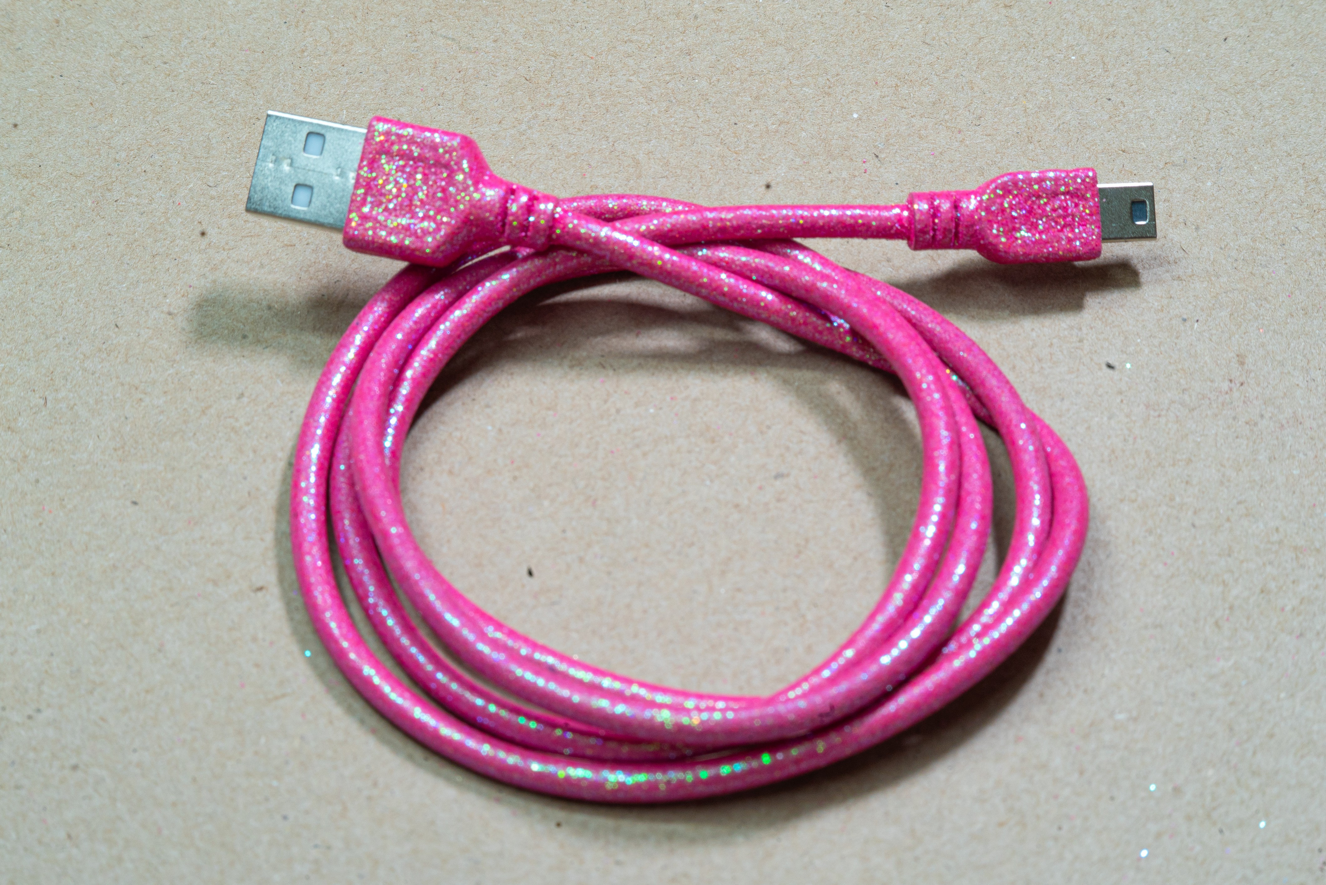
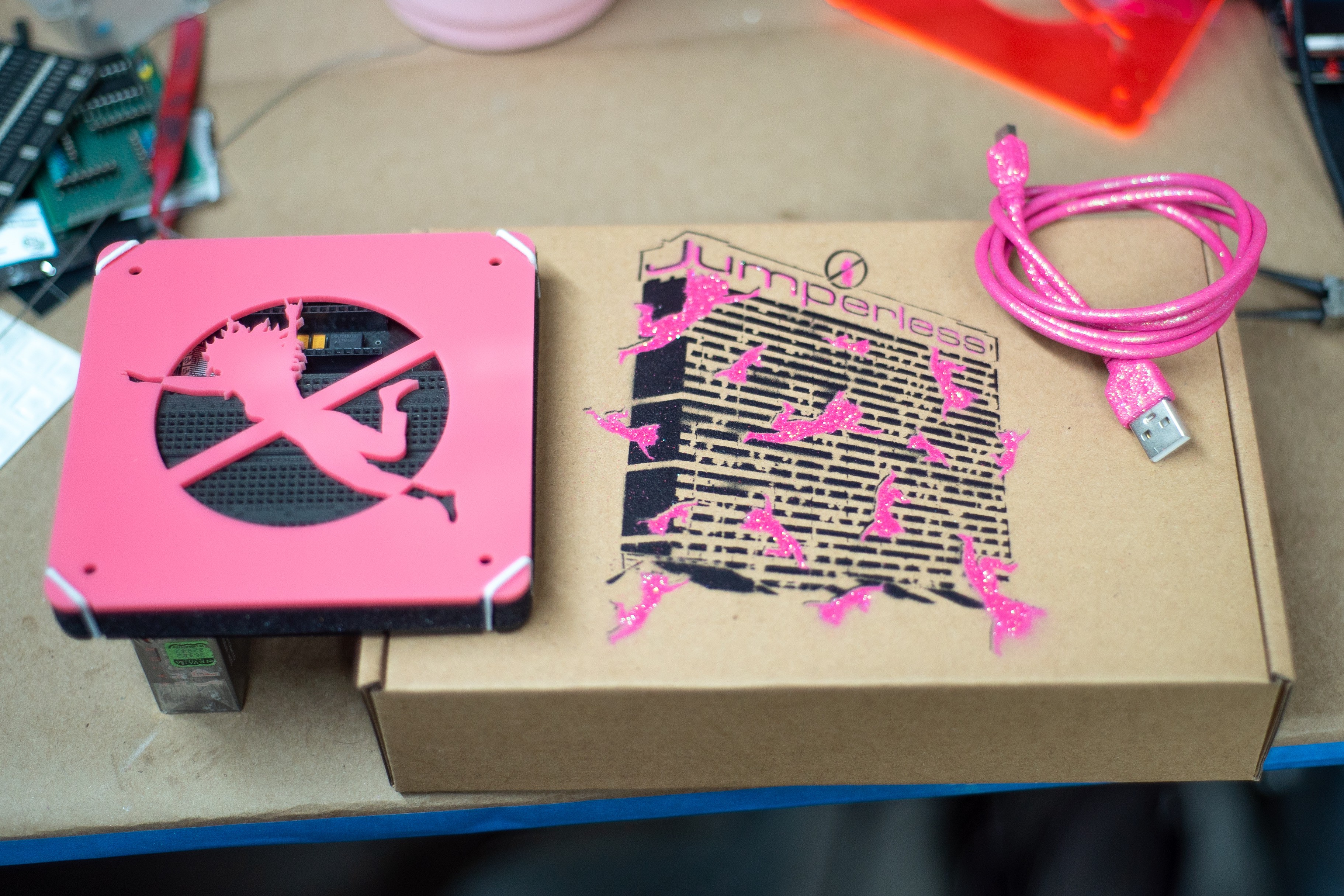
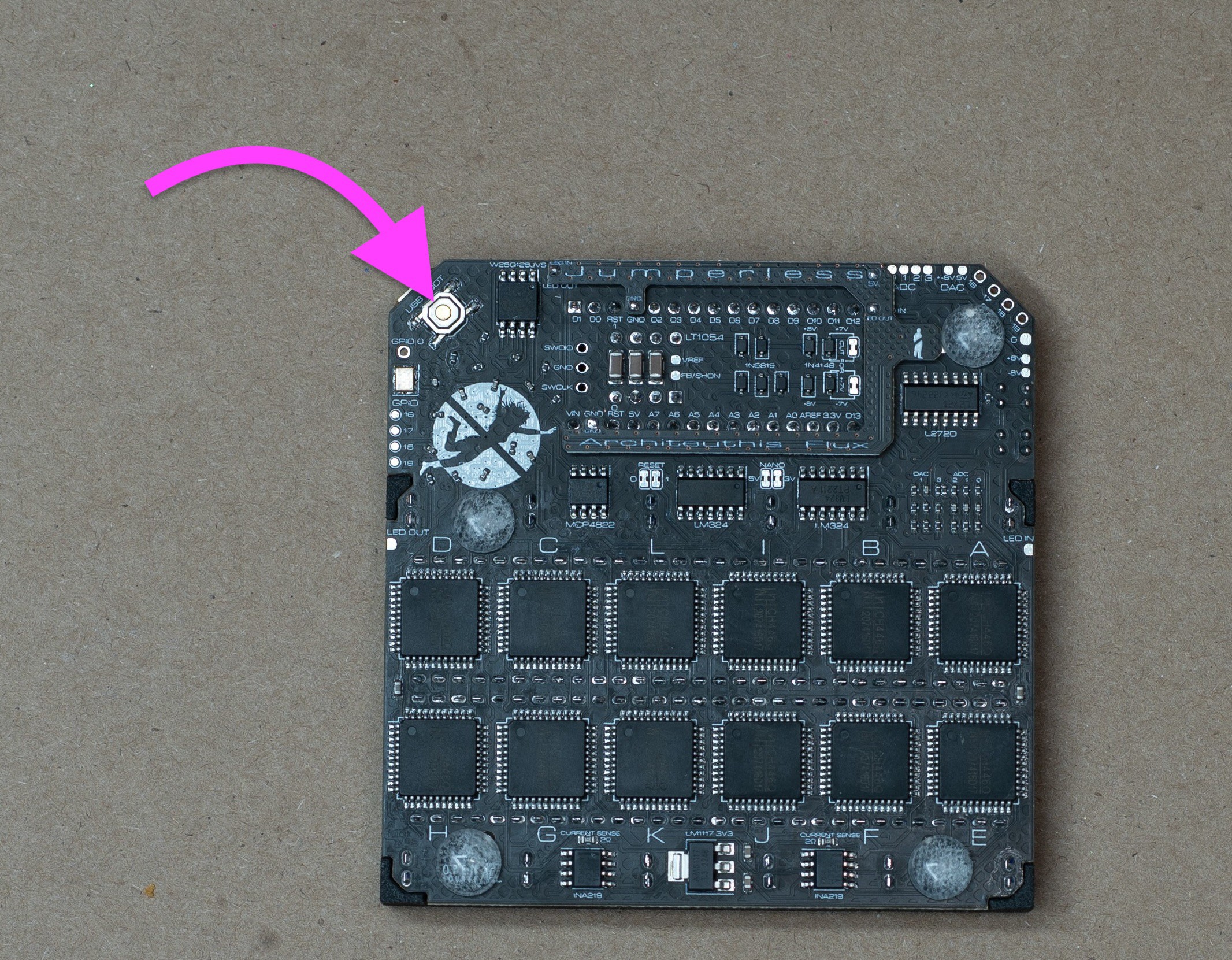
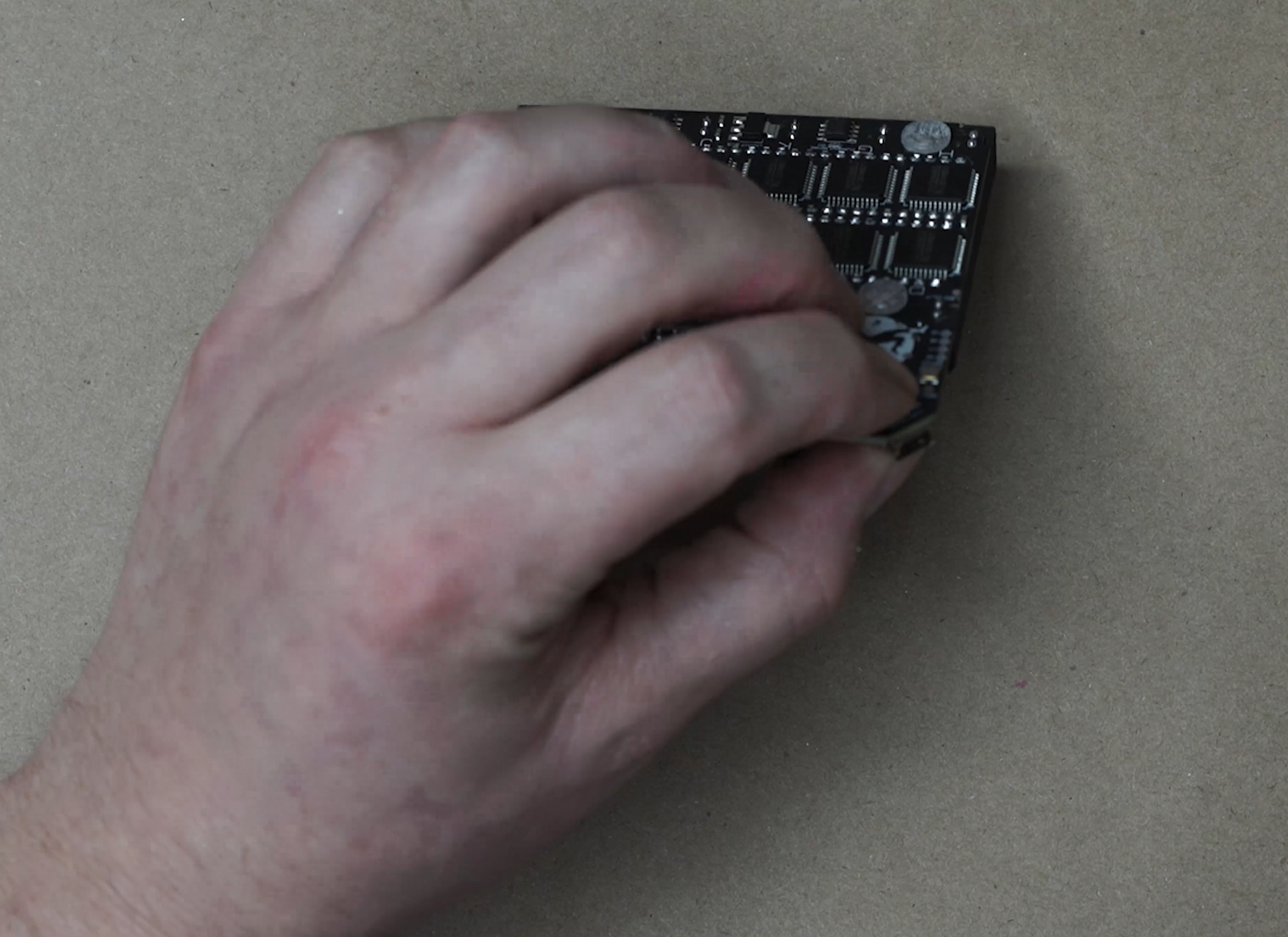
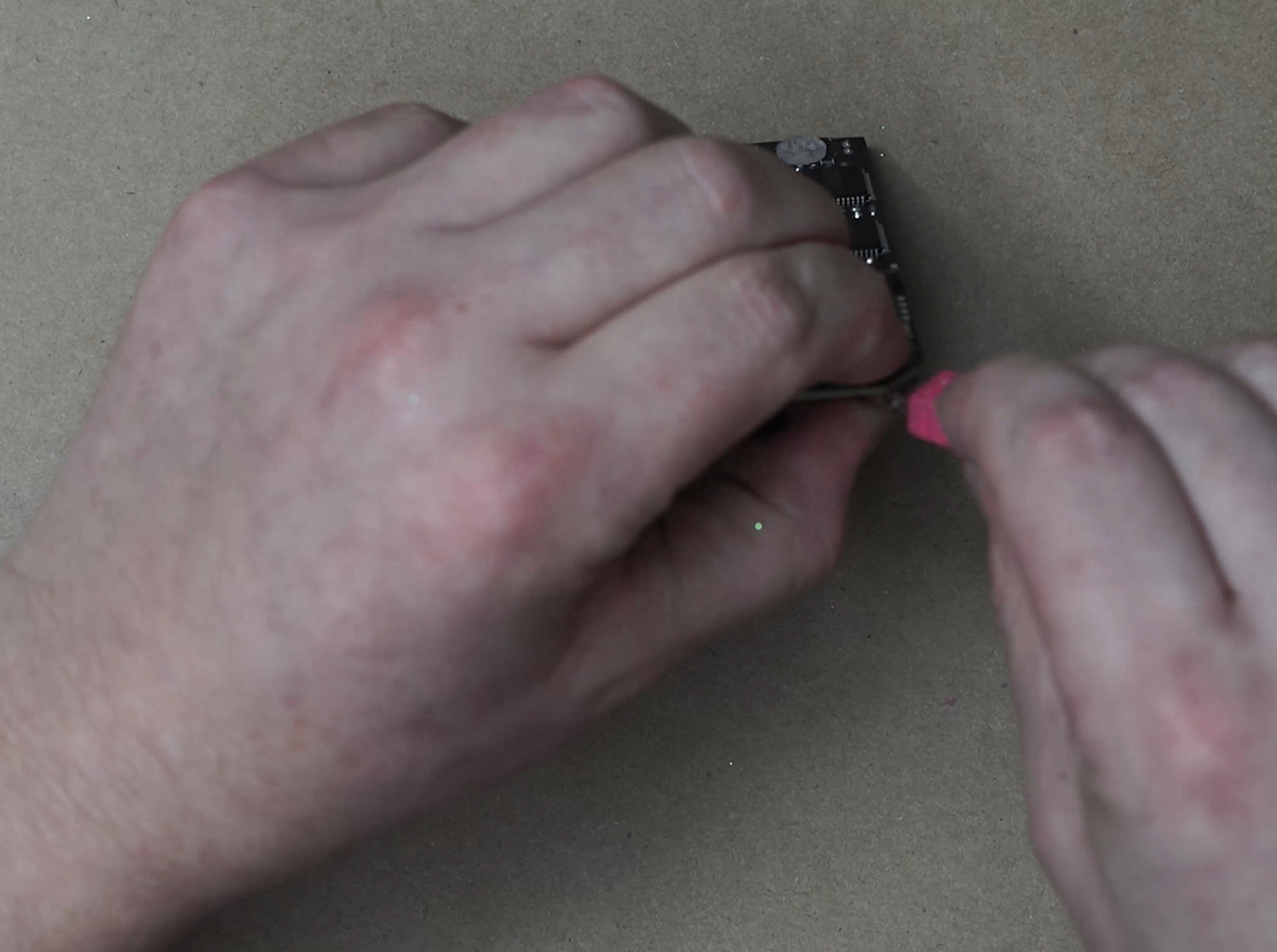
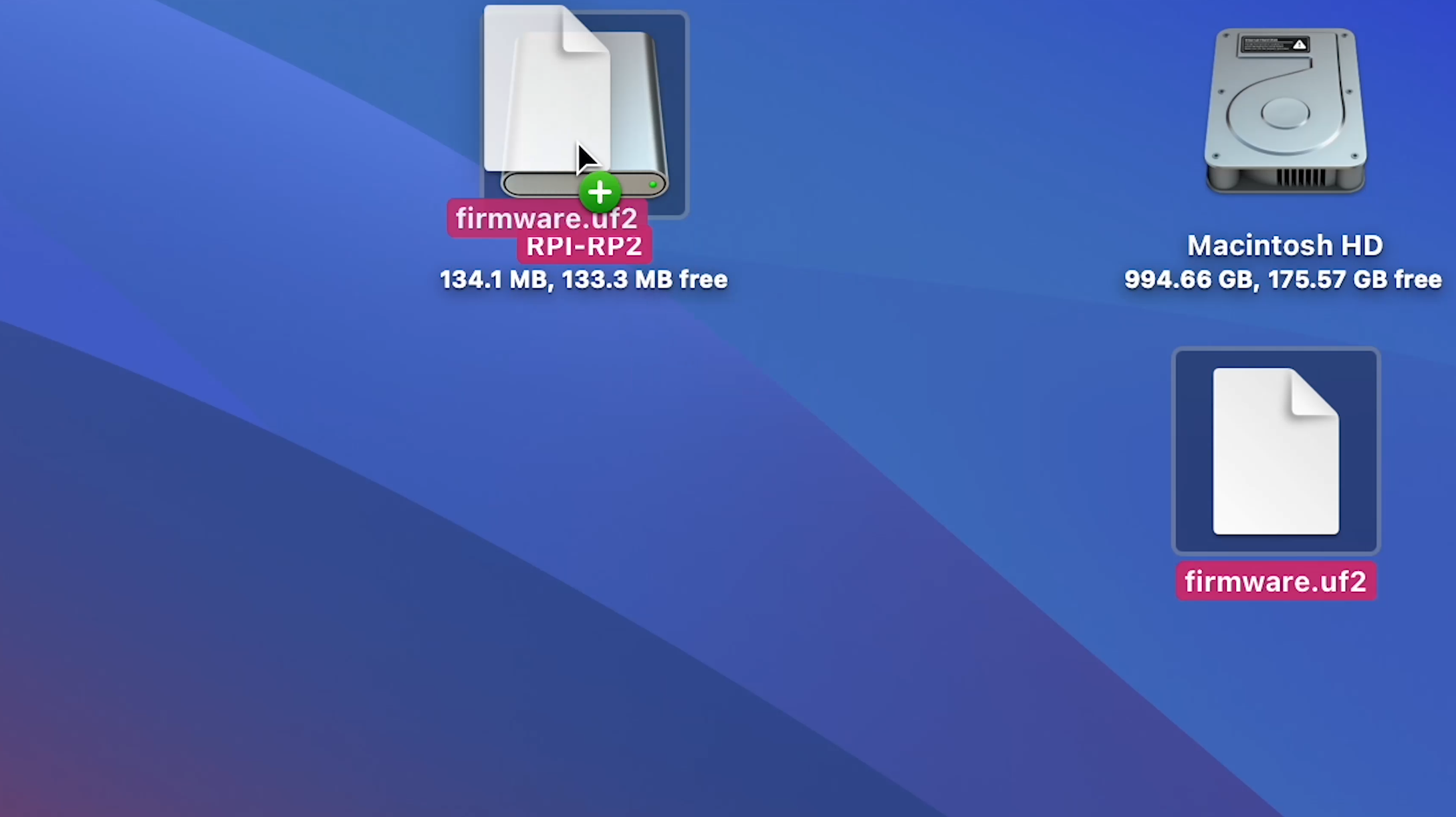
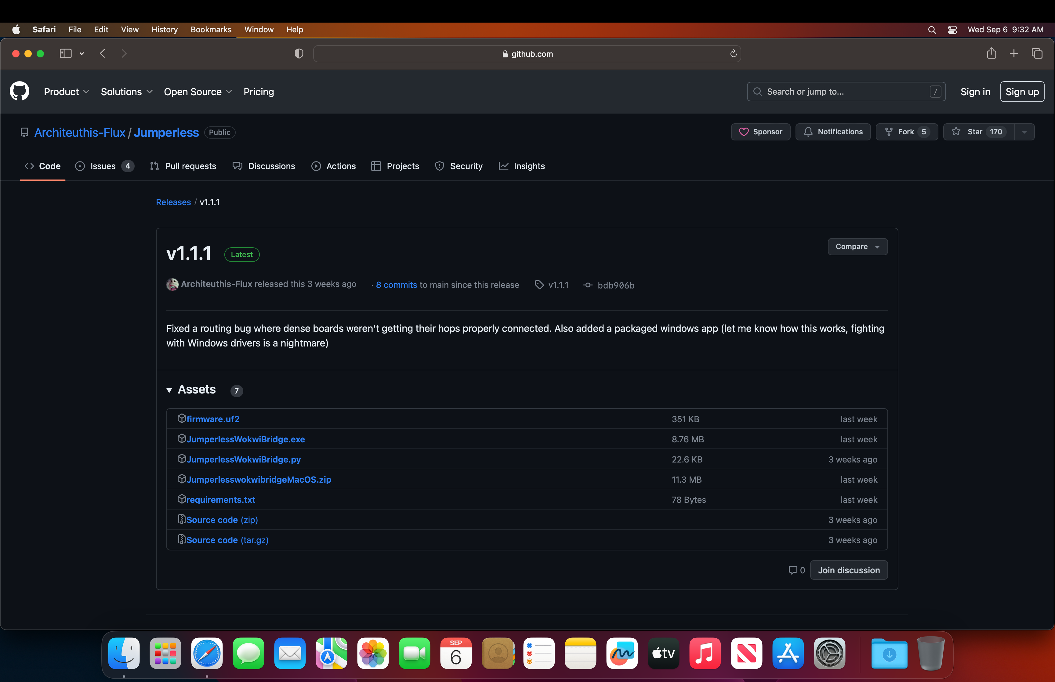
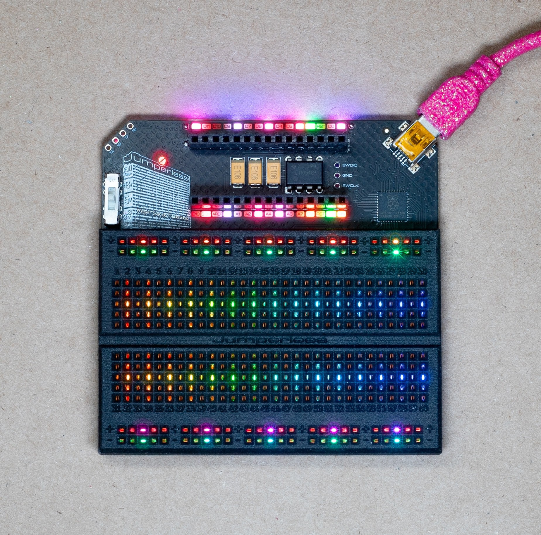
The Jumperless is controlled by an RP2040 and can be programmed exactly like a Raspberry Pi Pico. I spend every waking second of my life working on the firmware so there will be frequent updates. There are prebuilt UF2 files on Github under Releases, so whenever there's an update, just hold the USB BOOT button while plugging it into your computer (with the included pink glittery USB Mini cable,) then drag that UF2 file into the drive that pops up and you're good to go.
The whole thing is open source so you can also edit/fix the firmware however you like (and please submit a pull request on Github to share your fixes)
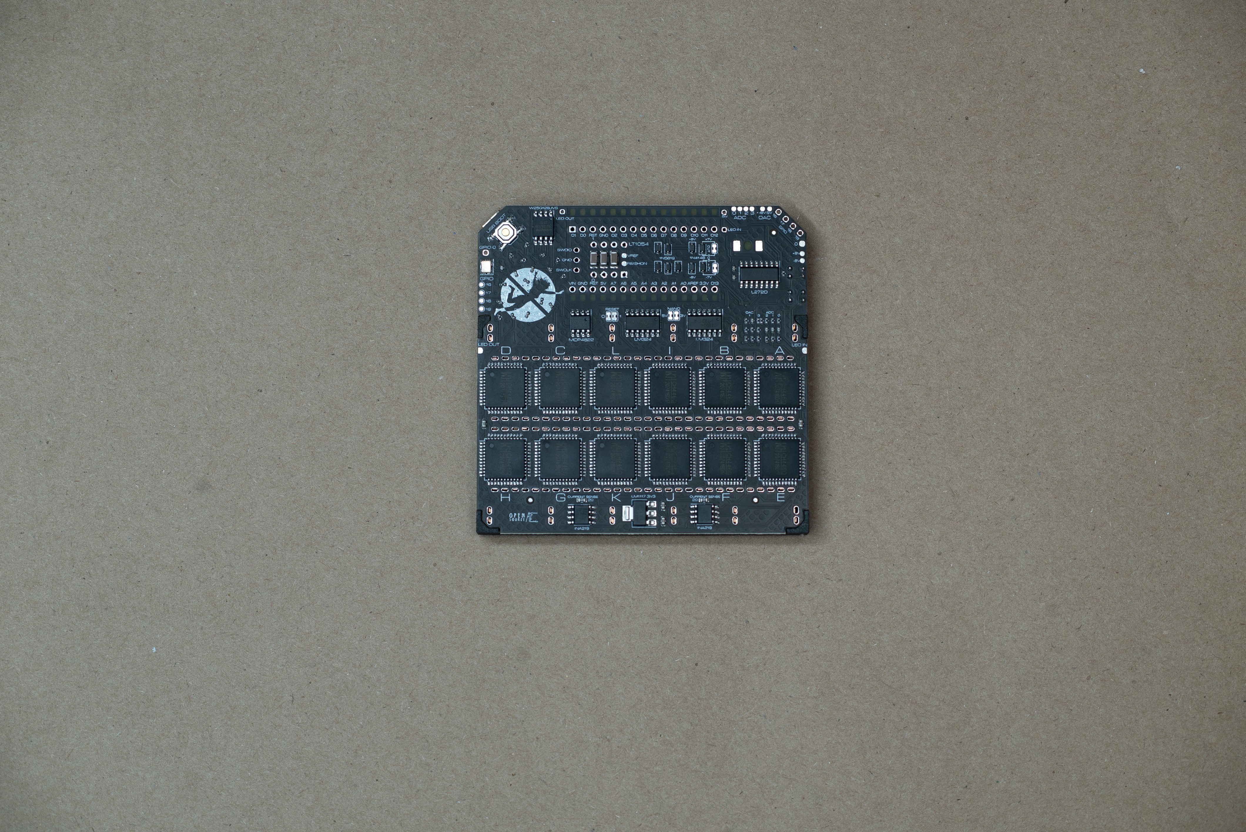
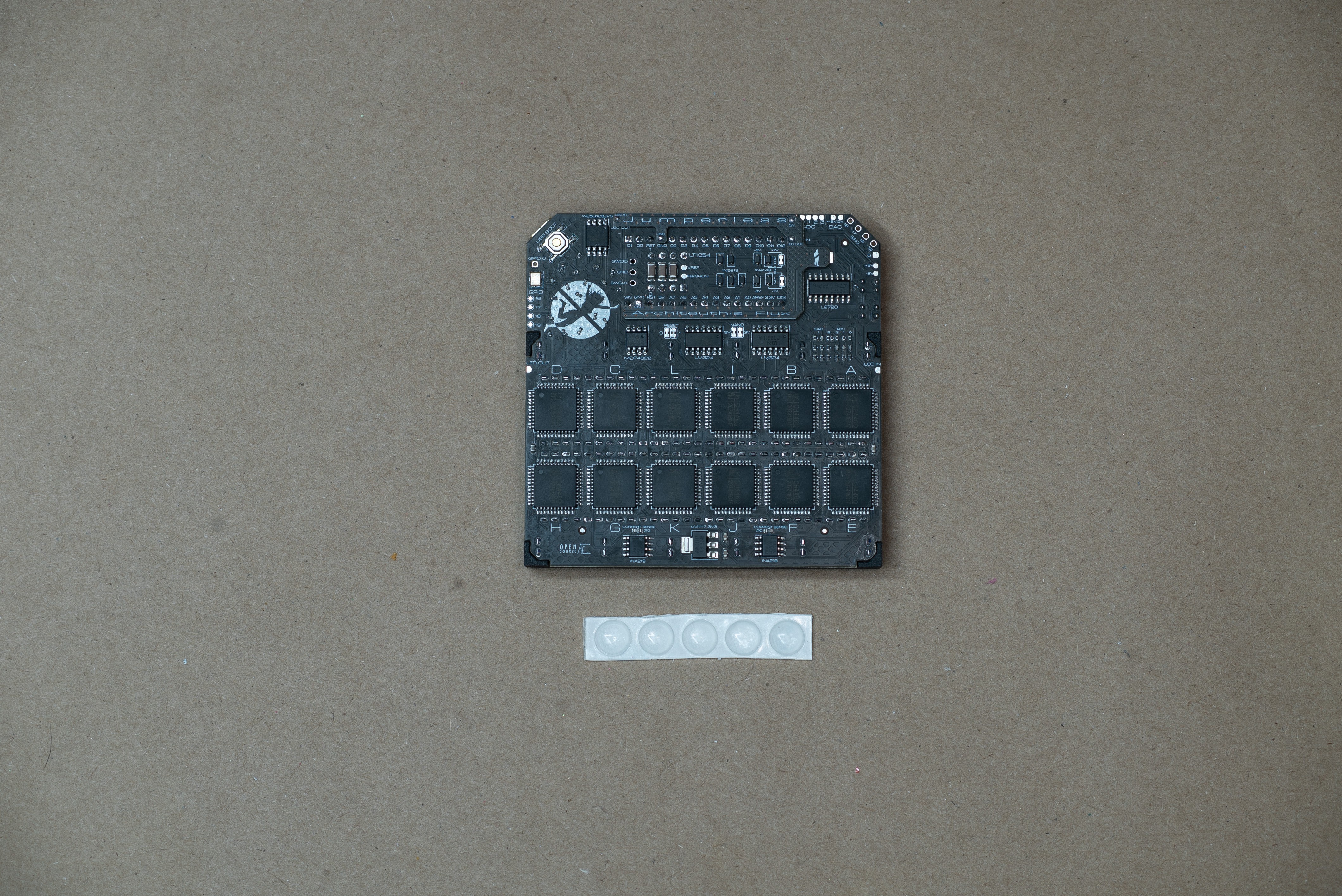
DACs and Revisions
Rev 3.1 is the current revision.
Revision 2 uses 2 MCP4728 12-bit I2C DACs, which work great for setting voltages to be used as an adjustable power supply, but I2C isn't fast enough to send clean waveforms above ~100Hz.

Revision 3.1 now uses a single MCP4822 2 channel SPI DAC, which is fast enough to make waveforms well above 400KHz. So you could feasibly use the onboard DAC as a Max8 or plugData output, and route the audio output to the breadboard and mess with it in hardware and even send it back in as an input. The software to do that hasn't been written yet but with the upcoming Python Module and Arduino API, it shouldn't be too difficult pull off.
Both of these revisions have their DACs buffered through an LM272D High Power (1A) op amp. Obviously 1 amp would blow this thing up, the power supplies couldn't handle it, and it would...
Read more »


 Marsupilami
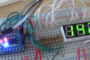
 Andrew Clapp
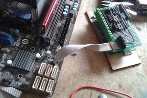
 Arya
Arya
Great job! Could I translate your work to vietnamese and share to our community with original link include ?